


This article was automatically translated from the original Turkish version.
+2 More
Full Authority Digital Engine Control (FADEC) is an integrated electronic system that provides complete digital control of gas turbine engines in modern aircraft. FADEC is a software-based control system that digitally monitors and manages all engine operating parameters to achieve optimal performance without requiring pilot intervention. This system real-time controls and regulates all processes necessary for engine operation including fuel injection, compressor and turbine geometry, ignition and other functions. Its primary objective is to provide a superior engine control infrastructure compared to traditional mechanical-hydraulic systems in terms of reliability, safety, fuel efficiency and maintenance ease.
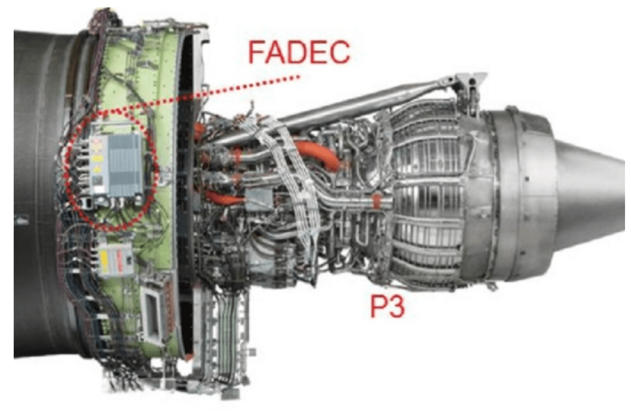
(Credit: Michael Usrey)
The emergence of Full Authority Digital Engine Control (FADEC) systems stemmed from the need to overcome the limitations of analog and electro-hydraulic control systems in aviation. In the late 1970s, as demand grew for more precise, faster and integrated control systems in aircraft engines, advances in microprocessor technology paved the way for electronically controlled engine management systems.
The first FADEC systems began to be used in military aviation applications in the early 1980s. During this period, electronic control evolved from being merely supplementary to fully assuming all engine control functions, transitioning from classical “supervisory” systems to full authority digital control systems.
These first-generation FADECs played an important role in enhancing flight safety and fuel efficiency by real-time monitoring of critical gas turbine engine parameters such as rotor speed, turbine temperature and fuel flow. FADEC systems became widely adopted in aircraft such as the F/A-18 Hornet, Eurofighter Typhoon and Boeing 777.
Three main stages can be identified in the evolution of FADEC systems:
For example, in recent years the Trent series engines developed by Rolls-Royce have incorporated model predictive control methods alongside traditional PID algorithms. Additionally, FADEC adoption has begun in the General Aviation sector. Manufacturers such as Lycoming (iE2 FADEC) and Continental (PowerLink FADEC) are developing FADEC applications for piston engines.
From the 1980s onward, the use of digital control systems in aviation required not only engineering innovation but also a regulatory transformation. FADEC software began to be developed in compliance with certification protocols such as RTCA DO-178 and DO-254. These standards mandate that FADEC software and hardware components be classified according to their criticality for flight safety. For instance, FADEC software classified as DAL-A, which contains the highest safety-critical functions, undergoes rigorous testing and validation processes.
Furthermore, the development of FADEC systems has driven the advancement of functional safety assessment methods such as FMEA, FTA and FHA. Particularly in single-engine aircraft, where FADEC failures directly impact flight safety, fault tolerant architectures have become widespread.
Next-generation FADEC systems are no longer limited to large passenger and military aircraft but are also being adopted in smaller and lighter aircraft. Research has focused on developing modular FADEC systems for small turbojet engines in the 1500 N thrust class. Such systems are used in specialized applications including gliders, unmanned aerial vehicles, powered gliders and auxiliary power systems.
Mini FADEC systems developed in this context are optimized for low weight, low power consumption, modular software-mechanical structure and PID-based control algorithms. Additionally, these systems incorporate data collection and fault diagnosis capabilities for training and research purposes.
The current development direction of FADEC systems is concentrated on the following four areas:
In conclusion, FADEC systems have become not merely an engine control system but the digital backbone of a comprehensive flight safety and efficiency infrastructure.
The FADEC system consists of four main components:
The FADEC system is a software-supported, closed-loop digital engine control system that manages all functions of an aircraft engine in real time. FADEC systems consist of multiple integrated subcomponents, each of which plays a vital role in system functionality and flight safety.
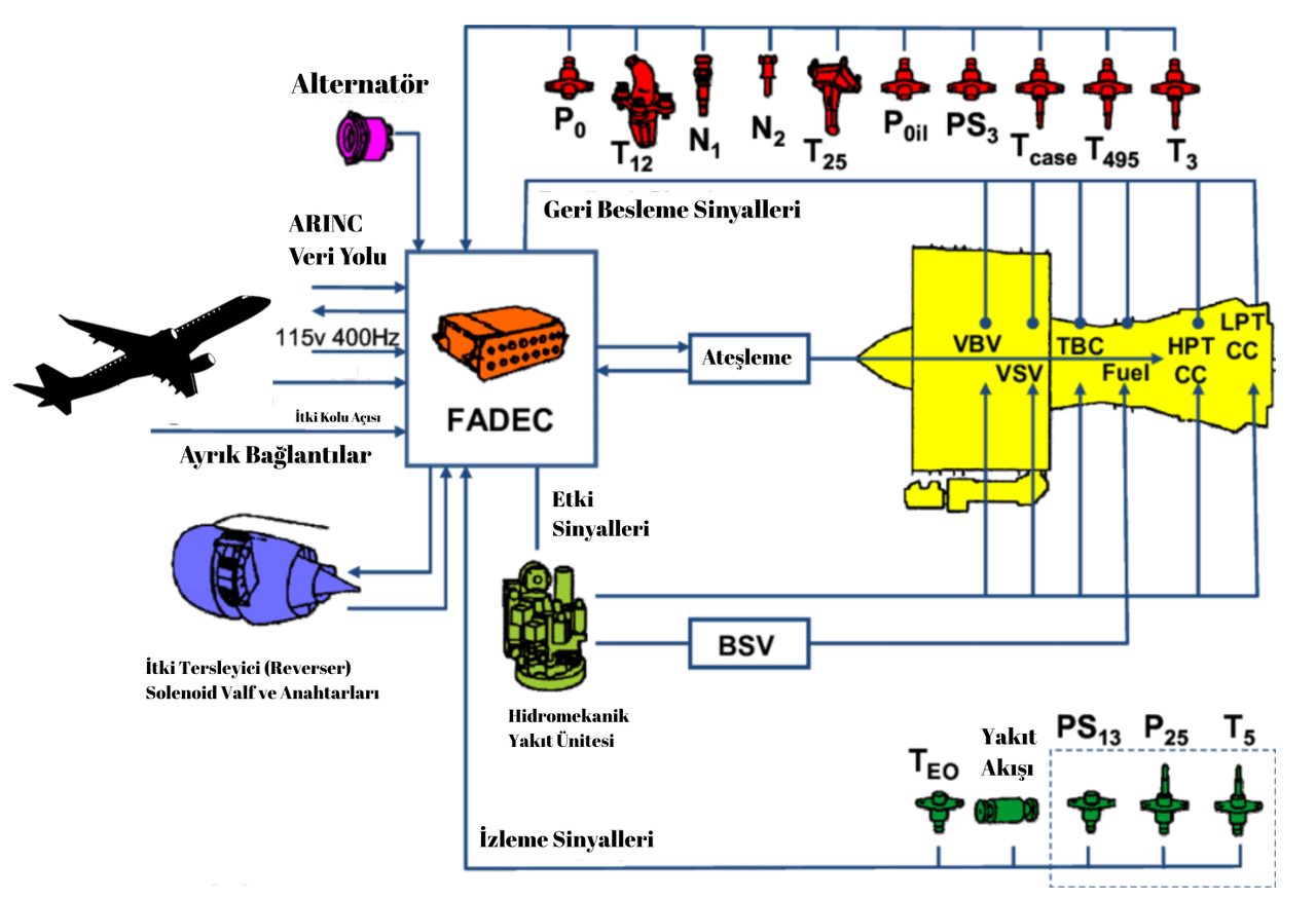
Editor: Beyza Nur Türkü (Credit: Alireza Behbahani)
FADEC systems generally consist of the following four main elements:
The Electronic Control Unit is the “brain” of the FADEC. It processes data from aircraft engine sensors and controls fuel injection, engine geometry (e.g. variable nozzles, fan or compressor blades), ignition timing and protection limits. The ECU hardware infrastructure consists of:
Embedded software within the ECU ensures the engine operates at its optimum performance point depending on flight regime. Modern ECU architectures are dual-channel (redundant); one channel operates actively while the other remains in standby, or both channels operate simultaneously comparing control values.
The HMU is the physical component that directly manages fuel flow according to signals from the electronic control unit. This unit consists of the following subcomponents:
The purpose of the HMU is to adjust fuel flow to meet engine power demands without exceeding safe operating limits. In failure scenarios, the HMU switches to a fail-safe mode to prevent the engine from entering hazardous regimes.
The FADEC system operates using data from numerous sensors across the engine and airframe. These data form the basis of the system’s closed-loop control. Typical sensors include:
Analog signals from sensors are digitized via A/D converters and processed by the ECU. Signal filtering, fault diagnosis and multi-source control algorithms are applied to protect against data loss, noise and corruption.
The following electrical connections ensure reliable data and power transmission between all FADEC components:
FADEC systems operating in high electromagnetic environments undergo EMI testing to ensure the durability of these components.
FADEC systems operate according to the principle of full authority digital closed-loop control. The system’s operation can be summarized in the following steps:
This process is repeated in millisecond time intervals, enabling FADEC to respond instantly to engine behavior. Additionally, during flight the FADEC system:
In modern FADEC systems, emergency mode functions and redundancy layers (mechanical backup or dual ECU architecture) ensure flight safety even in the event of system failure.
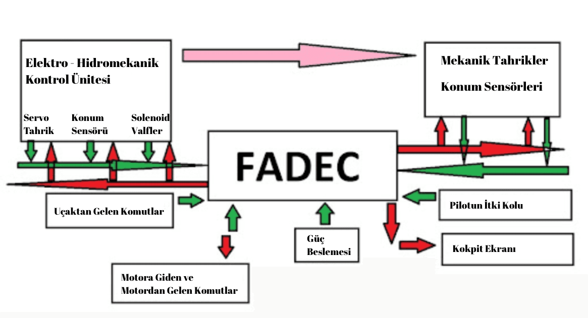
Editor: Beyza Nur Türkü (Credit: Aircraft Nerds)
The development of FADEC systems is subject to high standards that simultaneously meet numerous criteria such as airworthiness, reliability, environmental compatibility and maintenance ease. The development process is not limited to hardware selection and integration; the system must be supported by a software architecture that is safe, deterministic and optimized. Therefore, FADEC software is designed using advanced engineering techniques incorporating modularity, multi-layered programming, task prioritization and fault-tolerant control.
The following steps are followed in the development of FADEC systems:
1- Scenario and Requirement Definition
System requirements are defined to cover the entire lifecycle of the aircraft engine. Scenario analyses (takeoff, flight, failure, maintenance, shutdown scenarios) identify critical control points such as conditions requiring power retention, power cutoff and cooling durations.
2- Functional Definition
Each FADEC function (fuel metering, engine speed limiting, engine start, engine shutdown, flight data transmission) is systematically defined. Requirements for each function are linked to flight scenarios to ensure traceability.
3- Modular Design and Function Separation
In software design, each control function (fuel control, ignition, temperature monitoring) is configured as separate modules. This enables code reusability, testability and ease of maintenance.
4- Redundancy and Fault Management Integration
The system is designed to operate redundantly (dual ECU, dual data channels). Software is synchronized to activate the backup component when a fault is detected in the primary component.
5- Real-Time Operation and Timer-Based Control
FADEC software operates on real-time operating systems (RTOS). Timers enable task scheduling at millisecond scales to match engine dynamics.
The software architecture of FADEC systems generally consists of four main layers:
1. Driver Layer
2. Adaptation Layer
3. Functional Layer
4. Interaction / Interface Layer
This layered structure ensures both functional isolation and ease of maintenance. Additionally, this structure provides advantages in terms of traceability and safety during the airworthiness certification process.
The control algorithms used in FADEC systems are designed at different levels to ensure safe and efficient operation under flight conditions. These algorithms are generally classified into the following groups:
1. Classical Control Algorithms (PI, PID)
2. Optimal and Advanced Control (LQR, LQG/LTR)
3. Model Predictive Control (MPC)
4. Artificial Intelligence-Based Control (ANFIS, NARX)
The developed software must be validated at various test levels. The following methods are used for this purpose:
The software development process is conducted in accordance with aviation authority standards DO-178C (software safety assurance) and ARP 4754A (system development). Under these requirements:
Since FADEC systems perform critical control functions of aircraft engines, their hardware and software must meet the highest levels of reliability and safety. Therefore, the design, manufacturing, testing and commissioning processes of FADEC systems are regulated by strict certification protocols and international standards.
The certification process aims to document that the system meets both functional safety and airworthiness criteria. The process encompasses not only whether the software functions, but also under what conditions, how it functions, how it responds to faults and how it fulfills systematic safety objectives.
FADEC certification is primarily conducted by the following regulatory bodies:
Technical standards accepted by these authorities serve as reference documents that must be followed during the development of FADEC software and hardware.
The following key technical standards are considered during FADEC certification:
FADEC certification generally consists of the following stages:
1- Definition of Functional Requirements:
The system is defined according to flight modes. The specific functions of the FADEC are clearly determined.
2- Safety Assessment:
FHA/FMEA/FTA methods are used to analyze the potential effects of FADEC failures and assign a DAL level.
3- Development Process and Traceability:
Under DO-178C/DO-254, end-to-end traceability is established from requirements to test results for all software and hardware components.
4- Validation and Testing:
SIL (Software-in-the-loop), HIL (Hardware-in-the-loop), EMI/EMC tests, high temperature, humidity, vibration and voltage conditions are used to test the system.
5- Independent Audit and Review:
FAA/EASA representatives or independent verification organizations audit the project process, documents, test results and error logs.
6- Flight Test and Approval:
The developed FADEC system is tested under real flight conditions on a prototype aircraft. Certification is completed when the system successfully meets safety and performance criteria.
The certification process encourages the design of FADEC systems with fault-tolerant architectures. To this end, applications such as dual ECU (dual redundant control), TMR (Triple Modular Redundancy) architectures, cyclic error control (EDAC, CRC) and self-testing software processes (BIST) must be integrated into system design.
Additionally, the assumption of “perfect-from-start” is abandoned, and the impact of latent faults and incomplete repairs during flight is modeled and incorporated into certification.
FADEC systems are equipped with advanced control algorithms to ensure that the engine operates at optimum performance and safety at all times. The limitations of traditional PI/PID controllers and the highly variable, nonlinear nature of engine performance have made the use of more modern, adaptive and predictive control approaches necessary in FADEC systems.
Modern control methods not only balance engine performance but also achieve multiple objectives such as emission reduction, fuel consumption optimization, fault tolerance and rapid adaptation to flight conditions.
Traditional PID (Proportional-Integral-Derivative) controllers are preferred in FADEC systems, especially under steady conditions and low dynamic demands. For example, PID control is widely used in small turbojet engines. Advantages include simplicity of implementation and low computational cost.
However:
Due to these limitations, more advanced control algorithms have been developed.
LQR operates using a quadratic cost function that aims to stabilize the engine system while minimizing control effort. LQR usage in FADEC is particularly effective in regimes dominated by linear models.
LQG is an advanced form of LQR and is suitable for systems with random noise and measurement errors. With LTR, system fault tolerance is enhanced to minimize performance loss. When integrated into FADEC software, it better manages uncertainties in engine dynamics.
Model Predictive Control (MPC) predicts future engine behavior and makes decisions accordingly. In each control cycle, an optimization algorithm simulates the system’s response over a defined time horizon and applies constrained optimization.
Application Features:
In modern FADEC research, learning algorithms are increasingly used to predict and control both linear and nonlinear engine behavior. These methods are beginning to replace classical approaches in complex, multivariable, multi-objective control problems.
These models enable simultaneous optimization of multiple objectives such as emission reduction, engine safety and fuel efficiency.
Modern control algorithms are designed not only to optimize a single performance criterion but to make decisions based on multiple objectives (power, emissions, response time, fuel consumption). In this context, evolutionary optimization techniques such as Genetic Algorithms (GA) are also used in FADEC control strategies.
Optimization Criteria:
Modern FADEC systems are supported by fault-tolerant control structures capable of maintaining stable and safe operation despite sensor failures, actuator deviations or environmental uncertainties.
These approaches are particularly critical in sensitive environments such as single-engine platforms.
For FADEC systems to be safely used in flight, comprehensive validation, verification and testing during development are critical. Simulation and ground test environments enable systematic evaluation of how the FADEC will perform under pre-flight scenarios.
These test environments allow both normal and abnormal operating conditions to be safely and controllably recreated. This enables the algorithmic accuracy, system safety, fault tolerance and environmental compatibility of the FADEC system to be tested and verified before flight.
Simulation environments serve three primary purposes in the FADEC development process:
Simulation environments use mathematical engine models that mimic engine dynamics, sensor feedback and control inputs over time. These environments enable the identification of potentially hazardous flight safety scenarios before flight.
Specialized Avionics Simulation Test Systems (AVIONSTS) developed for FADEC software run control software using software-based engine models in place of the actual engine. These systems use a multi-layered software architecture consisting of the following components:
These architectures simulate the pre-flight behavior of FADEC software with high accuracy while providing the ability to evaluate real-time fault scenarios.
Beyond software testing, FADEC systems must also be evaluated in ground test environments with actual hardware components. A ground test environment allows the FADEC to operate without direct connection to the engine, using electronic simulation of engine dynamics.
A typical ground test environment includes the following components:
Aircraft operate in complex and high-density electromagnetic environments, so FADEC systems must be tested for electromagnetic interference (EMI).
The purpose of these tests is to verify that the FADEC system continues to operate safely, accurately and predictably in electromagnetic environments.
Electromagnetic tests assess the FADEC’s resilience against the following risk scenarios:
Under these conditions, FADEC may experience deviations, interruptions, resets or erroneous fuel control commands. Therefore, electromagnetic tests are essential to consider FADEC as a critical component for flight safety.
Traditional EMI/EMC tests were conducted in anechoic chambers (environments that absorb EM waves), but reverberation chambers (reverberation rooms) are increasingly preferred for testing complex closed-loop systems like FADEC.
Advantages of Reverberation Chambers:
In a representative test, the FADEC system was exposed to electromagnetic field intensities exceeding 1000 V/m, and deviations in its analog/digital outputs were monitored. In such tests, a power deviation of ±1–2% is considered a functional failure.
Electromagnetic tests for FADEC systems are based on both civil and military aviation standards:
Civil Standards:
Military Standards:
Test Scenarios:
Typical equipment and setup components used in electromagnetic tests include:
This equipment enables monitoring of the system’s operating point (e.g. throttle position, fuel flow) to detect out-of-tolerance deviations.
The test validity criterion recommended by FAA Advisory Circular 33-28 is:
“No effect shall be observed on the functional characteristics of the system during EME exposure.”
This criterion is practically interpreted as follows:
To achieve successful EMI/EMC test results, the following design measures are applied in FADEC system design:
These design measures enable FADEC systems to operate reliably both in test environments and under real flight conditions.
Failures that may occur in FADEC systems are generally classified into three categories:
Latent faults are particularly critical because they may not be detected during system tests before flight. This has been clearly observed in mission models that reject the “perfect from start” assumption.
Among the most commonly used methods for reliability analysis in FADEC systems are:
1. FMEA (Failure Modes and Effects Analysis)
2. FHA (Functional Hazard Assessment)
3. FTA (Fault Tree Analysis)
These analyses are also used to determine the Design Assurance Level (DAL) assigned to FADEC components. For example, a failure that could cause engine shutdown is classified as DAL A and subjected to the strictest software validation processes.
Markov models are widely used to analyze the time-dependent failure behavior of FADEC systems. This approach is particularly effective for systems that are non-repairable, redundant or operate in multi-phase missions.
With Markov Modeling:
For example, in a study on the RM12 engine (JAS 39 Gripen), two different FADEC architectures were analyzed:
Latency, coverage and reconfiguration times were included in the model for both architectures, and it was found that the TMR architecture offered a lower probability of failure.
Another modern approach, the state-part method, analyzes FADEC subcomponents by classifying them according to their functions. In this method, each component is assigned to one of the following categories:
This method differs from classical series-parallel system analyses by focusing on functional dependencies. System reliability is calculated as a weighted sum of these component groups.
To enhance reliability, the following measures are commonly implemented in FADEC systems:
The purpose of these structures is not only to detect faults but also to ensure uninterrupted flight. Particularly in TMR architecture, if one channel reports a fault, the system continues operation based on the vote of the remaining two channels and isolates the faulty channel.
FADEC systems were originally developed as high-tech engine control solutions for large commercial passenger aircraft and military jet engines. However, due to hardware miniaturization, decreasing software costs and increased reliability, FADEC systems are increasingly being adopted in General Aviation (GA) platforms.
Fixed-wing piston-engine aircraft, small turbojet-powered training aircraft, unmanned aerial vehicles (UAVs), powered gliders, ultra-light aircraft (ULM) and civil aviation training systems are now candidates for FADEC integration.
The following technical and operational advantages support the preference for FADEC in general aviation:
For these reasons, FADEC systems are increasingly preferred not only in large jets but also in less complex and lower-cost aircraft.
The use of FADEC systems in piston-engine aircraft is rapidly increasing. Manufacturers such as Continental and Lycoming offer FADEC solutions for piston engines:
1. Continental PowerLink™ FADEC:
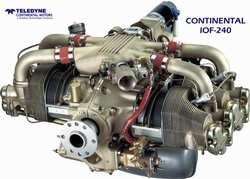
PowerLink Continental IOF-240 engine (Credit: Aero News Network)
2. Lycoming iE2™ FADEC:
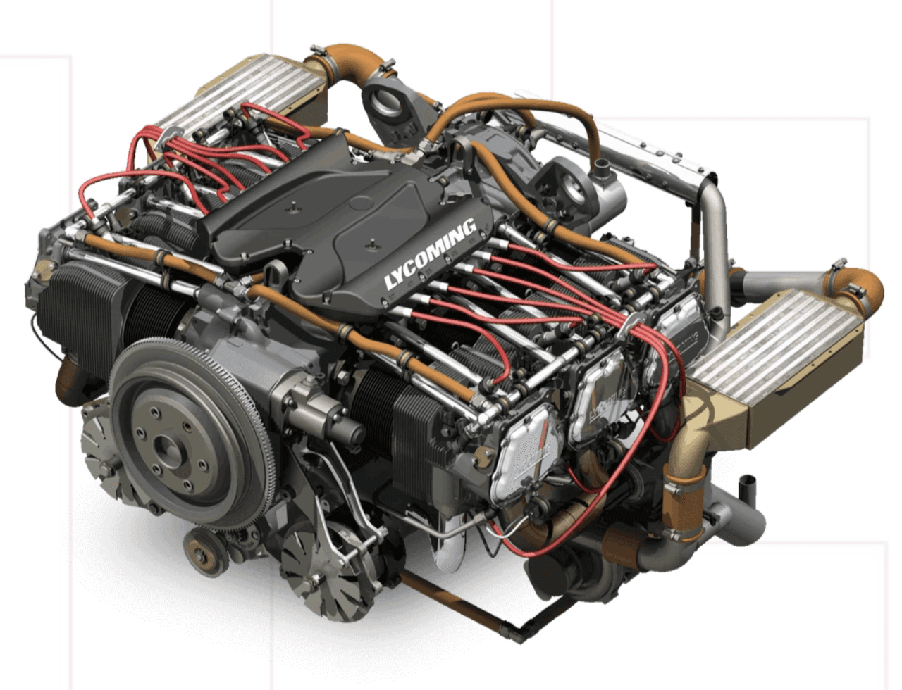
Lycoming iE2 Engine (Credit: Lycoming)
Thanks to these applications, pilots can focus on flying rather than engine internals. Additionally, engine life, fuel efficiency and maintenance cycles are improved.
Another growing application of FADEC in general aviation is in small-scale turbojet engines. These engines, used in training, research and civil UAV systems, have low thrust ratings (typically <1500 N). FADEC integration provides the following advantages for these engines:
For example, the FADEC architecture developed for the TKT-1 training turbojet engine provides a low-cost, simplified control environment using PID control algorithms; the system also includes data collection and fault diagnosis functions.
UAV platforms are increasingly benefiting from FADEC technology. Particularly in long-range, high-altitude or mission-critical UAV systems, the advantages provided by FADEC include:
FADEC systems developed for UAVs are generally designed to be smaller, lighter, lower power consuming and equipped with compact software architectures. They are also integrated using lightweight data communication protocols such as CAN-Bus.
Despite the growing adoption of FADEC in general aviation, some limitations and technical challenges remain:
Therefore, the widespread adoption of FADEC in the GA segment is often limited to specialized areas such as high-value training platforms, autonomous systems and technology demonstrators.

No Discussion Added Yet
Start discussion for "Full Authority Digital Engine Control (FADEC)" article
History and Development Process
Emergence of FADEC Systems
Development Stages and Next-Generation Architecture
Parallel Development with Software and Safety Requirements
Miniaturization and Integration into Lightweight Applications
Current Trends and Future Perspectives
Core Components and Operating Principle
Core Components
Electronic Control Unit (ECU)
Hydromechanical Metering Unit (HMU)
Sensors and Data Input Unit
Connection Elements and Electrical Interfaces
Operating Principle
Development Methods and Software Architecture
System Development Process and Requirements
Software Architecture
Control Algorithms
Testing and Validation Environments
Compliance with Certification Standards
Certification Process and Standards
Certification Authorities and Regulatory Bodies
Critical Standards
RTCA DO-178C / EUROCAE ED-12C – Software Certification
RTCA DO-254 / EUROCAE ED-80 – Hardware Certification
ARP4754A – Systems Engineering and Certification Process
ARP4761 – Safety Analysis
MIL-STD and FAA AC Documents
Certification Process Steps
Special Cases: Fault Tolerance and Redundancy
Modern Control Methods
Traditional Control Methods and Limitations
Optimal Control Methods
LQR (Linear Quadratic Regulator)
LQG / LTR (Linear Quadratic Gaussian / Loop Transfer Recovery)
Model-Based Predictive Control (MPC)
Artificial Intelligence and Data-Driven Approaches
ANFIS (Adaptive Neuro-Fuzzy Inference System)
NARX (Nonlinear Autoregressive with Exogenous Input)
Hammerstein-Wiener Models
Multi-Objective Optimization
Fault-Tolerant and Adaptive Control
Simulation and Ground Test Environments
Importance and Purpose of Simulation Environments
Avionics Simulation Software Architectures
Ground Test Environments and Components
EMI / EMC and Radiation Tests
Test Objectives and Importance
Test Environments: Anechoic vs Reverberation Chambers
Test Scope and Applied Standards
Test Structure and Equipment
Test Criteria: Definition of “No Effect”
Electromagnetic Compatibility Design Measures
Failure Types and Impact Classifications
Failure Modes and Effects Analysis (FMEA / FHA)
Markov-Based Reliability Modeling
State-Part Method for Reliability Assessment
Fault Tolerance and Redundancy Strategies
FADEC Use in General Aviation
Reasons for the Widespread Adoption of FADEC in General Aviation
FADEC Applications in Piston-Engine Aircraft
Use in Small Turbojet Engines and Training Systems
FADEC Use in Unmanned Aerial Vehicles (UAVs)
Challenges and Limitations