


This article was automatically translated from the original Turkish version.
Pneumatic systems are defined as systems that operate using compressed air. Pneumatic systems typically include cylinders, valves, and other mechanical components that are actuated by air or gas pressure.
Compared to other energy sources, air energy is readily available, inexpensive, and allows for faster operation in compact and short spaces. Air is drawn from the atmosphere using appropriate methods, stored, pressurized, and then released back into the atmosphere. The abundance of air in the atmosphere and its low cost of acquisition ensure economical operation. Pneumatic systems are used for various tasks in nearly every industry, including clamping and releasing workpieces, moving them, and achieving linear and rotary motion.
The fundamental operating principle of pneumatic systems is to use air or gas pressure to move a piston inside a cylinder. This movement generates force by pushing or pulling the piston within the cylinder. The force is applied at an connection point at the cylinder’s output, enabling mechanical motion.
Pneumatic systems generally consist of a compressor, an air reservoir, a control valve, and a cylinder or actuator. The compressor compresses atmospheric air or gas to generate air pressure in the reservoir. The air reservoir stores the compressed air or gas and prepares it for use. The control valve regulates the flow of air pressure from the reservoir to the cylinder. The cylinder or actuator then converts air or gas pressure into mechanical motion.
Compressed air used in pneumatic systems is supplied by compressors. Air production is typically provided by a centralized pressure source and delivered to the system via pipes or hoses. This eliminates the need for individual pressure sources for each user. For mobile machines or hand tools, portable compressors are used.
In selecting a compressor, determining the facility’s air demand (capacity) is a critical factor. Choosing a compressor with lower capacity than required reduces production efficiency and shortens the compressor’s lifespan due to frequent cycling. Choosing a compressor with significantly higher capacity than needed increases investment and operating costs.
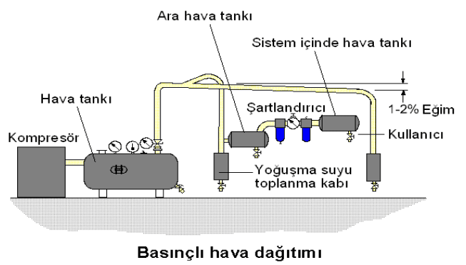
Compressed Air Distribution Diagram (Credit: Electrical-Electronic Technology, MEB, 2011.)
For system efficiency, it is essential to distribute the compressed air produced in pneumatic systems in a way that minimizes losses. When assessing current system requirements, future growth must also be considered. The system should be designed with future expansion in mind from the outset. Potential leaks in the compressed air distribution network must be anticipated from the beginning. Otherwise, future maintenance expenses and additional system installations may result in significantly higher costs.
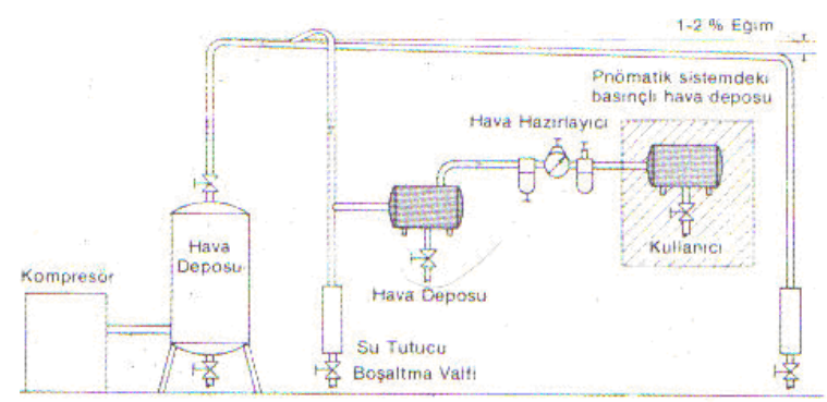
Compressed air distribution network (Credit: Electrical-Electronic Technology, MEB, 2011.)
Compressed air receivers are installed at the outlet of compressors. They prevent pressure fluctuations, provide additional surface area for cooling the compressed air, and facilitate condensation and separation of moisture.
Compressed air receivers can be horizontal or vertical. The air outlet must always be located at the top of the receiver. This prevents condensed water inside the receiver from entering the system.
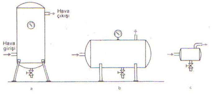
Installation configurations of compressed air receivers (Credit: Electrical-Electronic Technology, MEB, 2011.)
Three methods are used for drying air.
In this drying method, air is passed through a chemical substance that forms compounds with water. This chemical substance is sodium chloride, commonly known as “salt.” Water vapor in the air reacts chemically with this substance as it passes through and separates from the air, collecting at the base of the dryer as a solution. The solution must be periodically drained. Since salt gradually depletes, it must be replenished at regular intervals. The temperature of the incoming compressed air must not exceed 30°C. A filter must be installed after the dryer to capture any salt particles that may be carried into the air stream. Oil is also removed in this process. Due to the potentially harmful effects of excessive oil on the dryer, a fine filter must be installed at the inlet.
In this method, air is passed through a substance composed of silicon dioxide (silica gel). Water vapor is absorbed by the silica gel, which exists in granular form within the dryer. No chemical reaction occurs in this process. When silica gel comes into contact with water vapor, it changes color. Once it reaches saturation, it must be regenerated. Typically, two parallel dryers are used in this method. The saturated dryer is taken offline and dried by passing hot or cold air through it. The regenerated silica gel returns to its original color. Meanwhile, the other dryer remains in operation. Over time, silica gel particles may wear down and become airborne due to air flow. Therefore, a filter at the outlet is beneficial. Silica gel contaminated or worn by oil and other impurities should be replaced every one to two years.
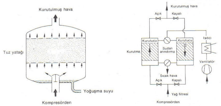
Chemical Drying Method and Physical Drying Method (Credit: Electrical-Electronic Technology, MEB, 2011.)
This method is based on cooling the air to its dew point, where water vapor condenses. The incoming air is first cooled slightly in a heat exchanger and then further cooled to approximately 1.7–5°C in a refrigeration unit. Condensation occurs simultaneously with cooling, separating the water vapor. The cooled air is then used to pre-cool the incoming air. A filter is used to remove dirt and oil particles from the cooled air. This method captures 80–90% of the oil originating from the compressor. It is the most widely used drying method due to its economic efficiency.
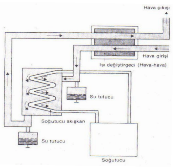
Cooling Method (Credit: Electrical-Electronic Technology, MEB, 2011.)
The air delivered to the point of use passes through a conditioning unit, known as an air preparation unit, consisting of a filter, pressure regulator, and lubricator, to achieve its final properties. An air preparation unit can also be briefly referred to as an FRY unit (Filter, Regulator, Lubricator).
The first component of the air preparation unit. Filters are used to separate foreign matter and water from compressed air. As air enters the filter, it passes through an inlet swirl chamber, creating a rotational motion. Solid particles and water collect on the inner wall of the housing due to centrifugal force. The air then passes through a sintered bronze filter element before exiting the filter. There are two methods for draining accumulated water from the housing. In manually drained filters, water must be drained before reaching the permissible level by opening the drain plug located at the bottom of the housing. In automatically drained filters, this process occurs automatically without human intervention.
Each pneumatic circuit has an optimal operating pressure. Excessively high pressure causes energy loss and rapid wear, while excessively low pressure prevents proper function or at least reduces efficiency. Since pressure in the compressor reservoir constantly fluctuates, a pressure-reducing valve (regulator) is required to prevent these fluctuations from affecting the system. Regardless of the inlet pressure, the outlet pressure remains constant at the value set on the regulator’s gauge. Regulators are divided into two types: vented and non-vented.
Lubricating a portion of the air used in pneumatic systems offers advantages such as minimizing wear, reducing losses due to friction, and providing protection against corrosion. Lubricators typically operate on the Venturi principle. As air passes through a narrow section, its velocity increases and pressure drops. This pressure drop creates suction from a fine oil line, causing oil to drip into the air stream. However, for dripping to occur, the air flow rate must exceed a minimum threshold; otherwise, the pressure drop is insufficient to draw oil. For proper lubrication, the lubricator’s adjustment screw is typically set to deliver 1–12 drops per 1000 liters of air. The viscosity of the oil used in lubricators at 20°C should be approximately 10–50 cSt. The distance between the conditioner and the farthest user should not exceed 5 meters; beyond this distance, the effectiveness of the sprayed oil diminishes.
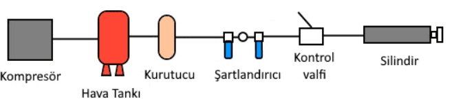
Pneumatic System Operating Diagram (Credit: Maktoloji)
Pneumatic cylinders convert compressed air energy into linear pushing or pulling motion. A pneumatic cylinder consists of front and rear caps, a cylinder barrel, a piston rod, and sealing elements.
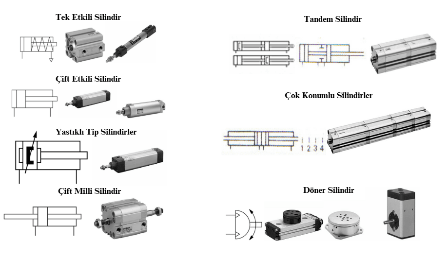
Types of Pneumatic Cylinders (Credit: Electrical-Electronic Technology, MEB, 2011.)
Air motors convert compressed air energy into rotary motion. Their most important features are their compact size relative to their power output and their ability to be easily controlled over a wide speed range due to their favorable torque characteristics. These motors can operate under harsh conditions such as heat, moisture, dirt, and vibration, and can be loaded to a complete stop without damage. They do not emit toxic gases and pose no explosion risk. Due to their adaptability, air motors are used across a wide range of applications, from large cranes on oil drilling platforms to small motorized air screwdrivers.
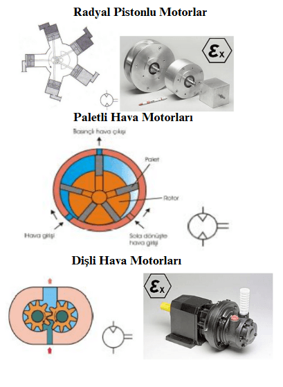
Types of Pneumatic Motors (Credit: Electrical-Electronic Technology, MEB, 2011.)
Pneumatic control circuits consist of a signal element, a control element, and an actuating element. The signal and control elements govern the motion of the actuating element. In pneumatic applications, these are referred to as valves. A valve controls the pressure, flow rate, direction, and start-stop conditions of a fluid from a hydraulic pump or pressurized tank. Based on their operating principles, valves are classified into three groups: directional control valves, flow control valves, and pressure control valves.
Squares are used to represent valves symbolically. These squares convey information about the valve’s function, not its construction.
Directional control valves are manufactured in two construction types: seat-type valves and slide-type valves.
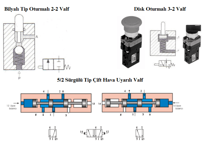
Directional Control Valves (Credit: Electrical-Electronic Technology, MEB, 2011.)
Pressure control valves are rarely used in pneumatic systems. A safety valve releases air to the atmosphere when the pressure reaches a preset value. They are used on air tanks.
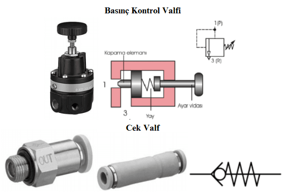
Pressure Control Valves (Credit: Electrical-Electronic Technology, MEB, 2011.)
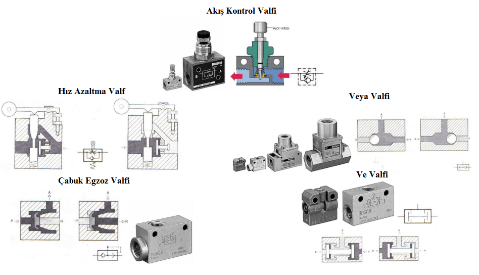
Flow Control Valves (Credit: Electrical-Electronic Technology, MEB, 2011.)
Pneumatic systems, widely used in industrial applications, are continuously updated and improved to enhance efficiency. The primary sectors using these systems are automation and robotics. Other sectors include food processing, textiles, cleaning, painting, filling, and packaging machines, assembly lines, and construction machinery.
Akyazı, Ömür, and Duygu Çokrak. "Pnömatik ve Hidrolik Sistem Uygulamaları." *Elektrik-Elektronik ve Bilgisayar Sempozyumu*, Elazığ, Türkiye, October 5–7, 2011, pp. 142–147.https://avesis.ktu.edu.tr/yayin/370f7c5c-4ee2-4f18-897e-39f81e92b9a9/pnomatik-ve-hidrolik-sistem-uygulamalari
Ankara Üniversitesi Açık Ders Malzemeleri. "Pnömatik Sistemler, Avantajları, Dezavantajları." Accessed [insert date if provided]. https://acikders.ankara.edu.tr/pluginfile.php/165741/mod_resource/content/0/6.Hafta-Pnömatik%20Sistemler%2C%20Avantajları%2C%20Dezavantajları%2CHidrolik%20Sistemlerle%20Karşılaştırılması.pdf
Doğuş Hidrolik. "Pnömatik Sistem Nedir?" Doğuş Hidrolik Blog.
Elektrik-Elektronik Teknolojisi, Milli Eğitim Bakanlığı. Pnömatik Sistemler. Ankara: MEB Yayınları, 2011. https://megep.meb.gov.tr/mte_program_modul/moduller_pdf/Pnömatik%20Sistemler.pdf
Kılıçaslan, Ertan. Pnömatik Sistem Elemanları. Master's thesis, Marmara Üniversitesi, 1988.
Zorlu, Ahmet. "Pnömatik Bir Sistemin Deneysel Modellenmesi ve Simülasyonu." PhD thesis, İstanbul Teknik Üniversitesi, 2002.

Principle of Operation of Pneumatic Systems
Structure and Operational Characteristics of Pneumatic Circuit Components
Preparation of Compressed Air
Distribution and Conditioning of Compressed Air
Air Drying
Chemical Method
Physical Method
Cooling Method
Air Preparation Components
Filter
Regulator
Lubricator
Internal Structure of Pneumatic Components
Pneumatic Cylinders
Pneumatic Motors
Directional Control Valves
Directional Control Valves
Pressure Control Valves
Flow Control Valves
Advantages of Pneumatic Systems
Disadvantages of Pneumatic Systems
Applications of Pneumatic Systems