Aircraft navigation instruments are systems that assist pilots in determining the correct direction and position during flight. These instruments are used to ensure safe movement of aircraft within airspace and to provide guidance during critical phases such as takeoff and landing gibi. Common navigation instruments used in aircraft include: ADF, DME, ILS, Localizer, Glide Path, Marker, NDB, VOR, TACAN, and VORTAC.
ADF (Automatic Direction Finder)
Principle of operation of Automatic Direction Finder
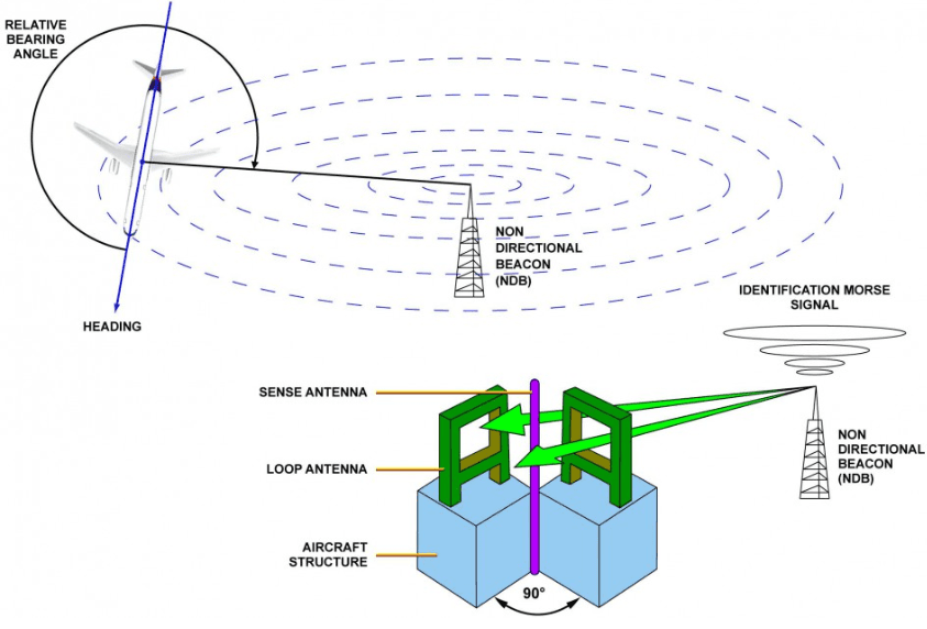
ADF (Automatic Direction Finder) is a navigation instrument that helps aircraft determine their direction. ADF is primarily used in aviation to enable aircraft to establish the correct heading and reach designated ground stations. The device enables the aircraft to determine the direction between its current location and a ground station, and typically operates in conjunction with a NDB (Non-Directional Beacon).
ADF is a device that assists aircraft in determining direction by receiving radio signals. These signals are typically transmitted by an NDB (Non-Directional Beacon). The ADF detects the signal and determines the direction of the aircraft relative to the NDB station. NDBs are radio transmitters located primarily on land, operating at a specific frequency and emitting omnidirectional signals. The ADF device receives these signals and functions like a compass to provide the aircraft with directional information.
The operation of ADF can be summarized as follows:
- NDB Station: The NDB continuously broadcasts radio waves that propagate toward the aircraft.
- Radio Wave Reception: The ADF device onboard the aircraft receives the radio waves emitted by the NDB.
- Direction Detection: The ADF determines the direction from which the signal is coming. This direction indicates whether the aircraft is heading toward or away from the NDB station.
- Direction Indication: The ADF device typically displays the direction to the NDB station using a compass-like indicator. This display helps the pilot steer the aircraft toward the station.
- Direction Determination: ADF is used by aircraft to establish the correct heading during flight. For example, by receiving a signal from an NDB, the aircraft can determine whether it is approaching or moving away from the station and adjust its flight path accordingly.
- Approach and Guidance: In low visibility conditions, ADF enables aircraft to orient themselves toward ground stations (NDBs). By receiving the NDB signal, aircraft can determine their bearing relative to the station and execute a safe approach.
- Weather and Visibility Conditions: During periods of poor visibility or adverse weather, the ADF device assists aircraft in maintaining the correct heading, ensuring continuous guidance under all conditions.
- Route Distance Management: Aircraft can follow their flight path by receiving signals from NDB stations located at specific distances. The ADF device helps aircraft accurately determine these distances.
Important Considerations for ADF Use
ADF is generally limited to receiving signals from NDBs. However, some aircraft may be equipped with devices capable of receiving multiple radio signals. Important considerations for ADF use include:
- Signal Sources: ADF receives signals exclusively from NDBs. Therefore, the presence of NDB stations in the aircraft’s operational area is critical. If the aircraft is flying over a region without NDB stations, ADF functionality may be severely limited.
- Signal Strength and Quality: NDB signals can sometimes be weak or subject to interference. In such cases, the ADF device may struggle to determine an accurate direction. Signal quality often deteriorates in mountainous or densely populated areas.
- Accuracy: Although ADF operates with high precision for direction determination, its directional indication may respond slowly when aircraft are moving at very high speeds. Therefore, ADF should be used as only one component of a broader navigation system during flight.
- Flight Planning: Aircraft typically follow flight routes based on NDBs. However, with the advancement of modern navigation systems such as GPS, the use of ADF has declined. Nevertheless, ADF remains a valuable navigation tool, especially in emergency situations and adverse weather conditions.
DME (Distance Measuring Equipment)
Principle of operation of Distance Measuring Equipment
DME (Distance Measuring Equipment) is a radio navigation device used to determine the distance between an aircraft and a ground station. DME enables aircraft to measure distances during takeoff and landing, or when approaching the nearest airports. This system assists pilots in accurately determining their position during flight.
DME typically operates in conjunction with VOR (VHF Omnidirectional Range), forming a combined system known as VOR-DME. DME can also be used alongside other systems such as ILS (Instrument Landing System) and TACAN (Tactical Air Navigation).
DME measures the distance between an aircraft and a ground station using radio signals. The system consists of two primary components: a ground station and an airborne receiver (transponder) onboard the aircraft.
- Signal Transmission (Ground Station): The ground station transmits a radio signal. When received by the aircraft, the onboard transponder responds by sending a return signal.
- Signal Reflection (Aircraft): The aircraft receives the signal from the ground station and replies with a return signal. The time taken for the signal to travel to the aircraft and back is measured.
- Distance Calculation: The ground station calculates the distance to the aircraft based on the time delay of the returned signal, using the known speed of radio waves. The DME device displays this distance as the slant range between the aircraft and the ground station.
This distance is typically displayed in nautical miles or kilometers. Another important feature of DME is its ability to measure distance very quickly, as radio signals travel at nearly the speed of light.
DME is widely used to enhance flight safety, track flight paths, and optimize flight performance. Its primary applications include:
- Direction and Distance Determination: DME helps aircraft determine both their direction and distance from ground stations. This is critical for air traffic control (ATC) and aircraft navigation.
- Takeoff and Landing: DME assists aircraft in determining their distance during approach for landing. Combined with ILS (Instrument Landing System), DME enables safe landings under low visibility conditions.
- Radar-Based Flight Tracking: Air traffic control (ATC) uses DME signals to monitor aircraft flight paths and detect potential deviations. Aircraft also use DME to determine their coordinates in airspace by measuring distances to ground stations.
- Flight Path Management: Aircraft can use DME to manage their flight routes more accurately and efficiently. For example, when flying along a VOR/DME route, aircraft can monitor distances and optimize their flight path.
- Military Flights and TACAN: DME is often used in conjunction with TACAN (Tactical Air Navigation) in military aviation. TACAN provides both direction and distance information for military aircraft and enhances flight safety.
DME consists of two main components: ground stations and airborne receivers. Both are critical for the proper functioning of the system.
1. Ground Station (DME Transponder):
- The ground station continuously transmits radio signals.
- These signals are received by aircraft to perform distance measurements.
- Ground stations can operate in conjunction with VOR or TACAN systems.
- Ground stations are typically located at airports or major aviation hubs.
2. Aircraft Receiver (DME Receiver):
- The aircraft receiver captures the signal from the ground station and transmits a return signal.
- The receiver is a device that calculates distance and typically displays the result on a screen integrated into the aircraft’s flight control system.
Advantages and Disadvantages of DME
Advantages:
- High Accuracy: DME provides highly accurate distance measurements, supporting safe aircraft navigation.
- Fast Response Time: DME calculates distance within seconds, enabling aircraft to determine their position rapidly and accurately.
- Integrated Systems: DME can operate in conjunction with other navigation systems such as VOR, ILS, and TACAN.
- Safe Landing Assistance: DME supports safe landings, particularly under low visibility conditions, by providing precise distance data during approach procedures.
Disadvantages:
- Signal Coverage Limitations: DME signals can be blocked or reflected by tall buildings or mountainous terrain, limiting the system’s effective coverage area.
- Distance Error: DME may exhibit reduced accuracy at very long distances or at extremely high altitudes.
- Frequency Congestion: DME operates within limited frequency bands, which can lead to interference in busy airspace where multiple systems operate on closely spaced frequencies.
ILS (Instrument Landing System)
Principle of operation of ILS
ILS (Instrument Landing System) is a navigation system that enables aircraft to land safely under low visibility conditions. ILS ensures accurate determination of aircraft position during approach and landing. The system assists pilots in controlling both direction and altitude, enabling safe landings even under adverse weather such as fog, snow, or rain.
ILS provides horizontal (Localizer) and vertical (Glide Path) guidance to keep aircraft aligned with the correct landing path and descend safely. For a successful approach, the aircraft must receive and correctly follow ILS signals.
ILS Principle of Operation
ILS generally consists of three main components:
- Localizer (Horizontal Guidance)
- Glide Path (Vertical Guidance)
- Marker Beacons
Localizer (Horizontal Guidance)
The Localizer provides the horizontal guidance necessary to align the aircraft with the runway centerline. This component emits a radio signal aligned with the runway. The aircraft receives this signal and adjusts its heading left or right accordingly.
- The Localizer signal is typically transmitted between 108.10 MHz and 111.95 MHz.
- The signal is broadcast linearly and aligned precisely with the runway centerline. The aircraft uses this signal to center itself on the approach path.
- If the aircraft receives the signal correctly, it remains on the proper centerline. If it deviates from the signal, the pilot must correct the heading.
Glide Path (Vertical Guidance)
Glide Path provides vertical guidance to ensure the aircraft maintains the correct descent altitude. This component directs the aircraft’s descent along a precise angle.
- The Glide Path signal is typically transmitted between 328 Hz and 335.4 Hz.
- The signal guides the aircraft to descend at a standard angle of approximately 3 degrees, ensuring a steady reduction in altitude.
- When the aircraft receives the Glide Path signal at a specific height above ground, it remains on the correct descent path.
Marker Beacons provide radio signals that indicate the aircraft’s position along the approach path and inform the pilot of remaining distance to the runway. Three types of markers are commonly used:
- Outer Marker (OM): This marker activates when the aircraft is near the beginning of the approach. Receiving the OM signal indicates the aircraft has entered the final approach path.
- Middle Marker (MM): Located at the midpoint of the approach, the MM signal indicates that the aircraft is at the correct altitude and has entered the final approach segment.
- Inner Marker (IM): The IM activates as the aircraft approaches the final point just before the runway threshold.
ILS Operation: Landing Process
ILS guides aircraft through several phases during landing:
- Approach: The aircraft enters the ILS system and aligns with the runway centerline using the Localizer signal. Simultaneously, the Glide Path signal establishes the correct descent angle. During this phase, the aircraft maintains alignment both horizontally and vertically.
- Corrections: If the aircraft deviates from the Localizer or Glide Path signal, cockpit indicators alert the pilot to make corrections. The aircraft adjusts its heading or descent rate to return to the correct path.
- Landing: After passing the Middle Marker, the aircraft prepares for final landing. As the aircraft nears the runway, the Inner Marker activates, signaling that the runway is immediately ahead. The pilot then completes speed reduction and landing procedures.
Advantages of the ILS System
ILS is a highly effective system for enabling safe landings under low visibility conditions. Its key advantages include:
- High Safety: ILS allows pilots to land safely even under poor visibility caused by fog, rain, or snow. Aircraft can rely on ILS for precise guidance when visual references are unavailable.
- High Precision: ILS ensures aircraft remain precisely aligned on both horizontal and vertical approach paths, reducing landing errors and enhancing flight safety.
- Integrated Systems: ILS often operates in conjunction with DME (Distance Measuring Equipment) and TACAN, allowing aircraft to receive both distance and directional data simultaneously for more accurate approaches.
- Short and Safe Landing Distance: ILS provides the correct descent rate and alignment, enabling safe landings at shorter distances from the runway threshold.
Disadvantages of the ILS System
- Signal Interference: ILS signals can be disrupted by interference from other radio frequencies, potentially compromising accurate approach guidance.
- Limited Coverage Range: ILS signals are effective only within a limited range. Signal accuracy decreases significantly at long distances.
- Dependence on Ground Stations: ILS relies entirely on ground-based transmitters. Any malfunction at the ground station can render the entire ILS system inoperative.
NDB (Non-Directional Beacon)
NDB (Non-Directional Beacon) is a radio signal source used to determine aircraft position and support navigation. NDBs play a crucial role in assisting pilots under low visibility conditions or when visual references are unavailable. The NDB emits a horizontal signal, allowing aircraft equipped with appropriate receivers to determine the direction toward the beacon.
- Omnidirectional Signal Transmission: The NDB emits a signal equally in all directions. This means the signal radiates 360 degrees uniformly, allowing aircraft to determine the direction of the beacon by receiving the signal.
- Frequency Range: NDBs operate in the MF (Medium Frequency) and LF (Low Frequency) bands between 190 kHz and 535 kHz. These frequencies allow signals to travel long distances, although with lower accuracy compared to higher frequency systems.
- Principle of Operation: The NDB functions as a radio transmitter. The aircraft’s receiver (ADF – Automatic Direction Finder) captures the signal. The aircraft then adjusts its heading based on the direction of the received signal, maintaining a course toward the NDB.
NDB and ADF Operating Principle
For the NDB to be used effectively, it must be paired with an ADF (Automatic Direction Finder) onboard the aircraft. The ADF receives the NDB signal and indicates its direction. This enables the aircraft to adjust its course and navigate accurately toward the NDB.
ADF Operation:
- The ADF receives the signal and determines the direction of its source.
- The aircraft uses the ADF reading to identify the direction and approximate distance to the NDB.
- The pilot uses the ADF to steer the aircraft toward the NDB.
For example, an aircraft receiving an NDB signal can determine the correct heading by observing the ADF display. The aircraft then follows this heading to approach the NDB.
Use of NDB in Aircraft Navigation
NDBs are essential tools for aircraft navigating toward local airports or passing specific waypoints, especially where visual references are absent. Aircraft use NDB signals to determine correct routes and altitudes.
Applications:
- Route Finding: When flying toward an NDB, the aircraft uses the ADF to determine the correct heading and maintain its flight path after departure.
- Approach and Landing: NDBs can be used during approach phases. NDBs located near airports help aircraft identify their landing path, especially at airfields lacking more complex systems like ILS (Instrument Landing System).
- Navigation Control: Aircraft can verify their course alignment by monitoring the NDB signal. If the signal is lost or deviates, the pilot can detect the error and make corrections.
- Long Range Coverage: Due to their low operating frequencies, NDB signals can propagate over long distances, enabling aircraft to receive them across wide areas.
- Simple Design and Low Cost: NDB systems are simpler in design compared to other navigation systems, resulting in lower installation and maintenance costs. This makes them particularly suitable for smaller airports or developing regions.
- Assistance in Low Visibility Conditions: NDBs provide pilots with reliable directional guidance under poor visibility caused by fog, rain, or snow, serving as a critical aid during flight.
- Signal Interference and Distortion: NDB signals can be affected by environmental factors such as buildings, mountains, or weather conditions, reducing signal accuracy and potentially leading to incorrect pilot guidance.
- Limited Directional Accuracy: Since the NDB signal indicates only a general direction, it is sometimes difficult to determine the exact location the aircraft is being directed toward. This results in lower precision compared to more advanced navigation systems.
- Limited Range: Due to their frequency characteristics, NDB signals have a limited range. Aircraft flying at very high altitudes or over long distances may have difficulty receiving the signal.
VOR (VHF Omnidirectional Range)
VHF Omnidirectional Range
VOR (VHF Omnidirectional Range) is a radio navigation system used to determine aircraft position and maintain accurate flight paths. VOR provides a more precise and advanced technology than the previously described NDB (Non-Directional Beacon) system. VOR functions as a directional guidance system that enables aircraft to navigate accurately toward specific points or routes.
Basic Components of the VOR System
The VOR system consists of several key components:
- VOR Transmitter: Located at a fixed point on the ground, this device broadcasts radio signals in all directions. VOR transmitters are typically situated around airports or at key airway junctions.
- VOR Receiver (Aircraft Equipment): Installed onboard the aircraft, this device receives signals from the VOR transmitter and determines the direction (radial) from the aircraft to the transmitter. This radial defines the aircraft’s bearing relative to the VOR station, enabling it to follow the correct course.
- Air Traffic Control: VOR is a vital tool for airports and airway routes, helping coordinate aircraft movements within controlled airspace.
Principle of Operation of VOR
The VOR system provides aircraft with 360 degree directional information. Each radial represents a specific direction. VOR transmits modulated signals that are received by the aircraft’s onboard receiver, which then determines the direction of the signal and establishes the correct flight path.
- The VOR transmitter emits radio signals that radiate equally in all directions, allowing the aircraft to detect the signal from any angle.
- The VOR receiver onboard the aircraft receives the signal and displays the direction as a radial. The aircraft then aligns its course with this radial.
- The pilot uses the directional information received from the VOR receiver to adjust the aircraft’s heading accordingly.
VOR signals provide aircraft with both radial (direction) and distance information, enabling them to determine their position relative to the VOR station.
VOR is a critical tool for aircraft navigation along airway routes. It is one of the primary navigation systems used to guide aircraft safely toward specific destinations. Aircraft can follow flight paths planned around VOR stations.
VOR provides aircraft with both directional and distance information, allowing pilots to accurately track their flight path during flight.
There are several types of VOR systems:
- Conventional VOR (CVOR): Standard VOR transmitters that broadcast radio signals. Aircraft receive these signals to determine radial and distance information.
- VOR Integrated with DME (VDME): This system integrates a VOR transmitter with a Distance Measuring Equipment (DME) unit. This allows aircraft to receive both directional and distance data simultaneously, enabling more accurate route tracking.
- VORTAC: A combination of VOR and TACAN (Tactical Air Navigation). This system provides both directional and distance information and is usable by both military and civil aircraft. VORTAC includes both VOR and TACAN transmitters, making it essential for military operations and busy air traffic corridors.
- VOR/DME: A combination of VOR and DME equipment. This system provides aircraft with both directional and distance information.
Aircraft can determine their correct course and navigate by referencing VOR transmitters. VOR radials define the direction aircraft must follow to reach their destination. Pilots use radial information to adjust their heading during flight.
In VOR navigation, aircraft typically follow this method:
- VOR Radials: The aircraft uses radial information along its route to determine direction. The VOR device provides the bearing from the aircraft to the target.
- Integrated DME: When VOR and DME are combined, aircraft receive both directional and distance data. This helps them determine the most efficient and accurate path to their destination.
Advantages of the VOR System
- High Accuracy: VOR provides more precise directional guidance than NDB, enabling aircraft to follow their routes with greater accuracy.
- Global Use: VOR is widely used at airports and along airways throughout the world.
- Wide Coverage Area: VOR systems typically have broad coverage, allowing aircraft to be accurately guided over long distances.
- High-Speed Operation: VOR is suitable for high-speed aircraft, as the signals are received quickly and allow for immediate course corrections.
Disadvantages of the VOR System
- Signal Interference: VOR signals can be affected by environmental factors such as mountains or buildings, or atmospheric conditions such as thunderstorms, which may degrade signal quality and accuracy.
- Limitations in Low Visibility: Although VOR is effective in low visibility, it has certain limitations under conditions of heavy air traffic or extreme weather.
- Outdated Compared to Modern Systems: Compared to GPS and other modern navigation systems, VOR is less precise and more limited. However, it remains widely used globally.
TACAN (Tactical Air Navigation)
TACAN (Tactical Air Navigation) is a radio navigation system developed specifically for military aircraft. Similar in structure to the VOR (VHF Omnidirectional Range) system, TACAN provides both directional (radial) and distance (range) information. Designed to meet the specific needs of military aviation, this system enables precise aircraft guidance and accurate flight path maintenance.
TACAN enables aircraft or military vessels to determine their position by receiving radio signals from a ground-based transmitter. This system also functions as an extension of the VOR/DME system, which is used by both military and civil aircraft.
- TACAN Transmitter: A ground-based device that transmits radio signals to aircraft. The TACAN transmitter provides both directional (radial) and distance (range) information. TACAN transmitters are typically located at military bases or strategic areas.
- TACAN Receiver (Aircraft Equipment): Installed onboard the aircraft, the TACAN receiver captures signals from the ground station and calculates both the direction (radial) and distance to the transmitter. The aircraft uses this information to determine its correct course.
- Air Traffic Control (ATC): TACAN is a vital navigation tool used by both military and civil aircraft. Aircraft use the TACAN system to receive directional and distance data and monitor air traffic.
Principle of Operation of TACAN
TACAN operates similarly to VOR but differs in its ability to provide distance measurements. The system simultaneously determines both the direction and distance between the aircraft and the TACAN transmitter, enabling more accurate guidance to the target.
- The TACAN transmitter broadcasts radio signals that radiate uniformly in all directions, allowing aircraft to receive 360-degree directional information.
- The TACAN receiver onboard the aircraft receives these signals and calculates both the direction (radial) and distance to the transmitter. The aircraft then follows the correct course based on this data.
TACAN signals consist of a “pulse” signal and an “azimuth” signal. These two signals together provide the aircraft with both directional and distance information, enabling more precise navigation toward the target.
TACAN is widely used in military aviation. Some civil aircraft may also use TACAN systems in conjunction with VOR/DME. TACAN is typically used in the following areas:
- Military Air Routes and Intelligence: TACAN enables military aircraft to navigate accurately and reach their targets with high precision.
- Military Vessels: Military ships can use TACAN to determine direction and distance at sea, enhancing navigation safety.
- Air Force Operations: Air forces use TACAN to track fighter aircraft routes and direct them toward specific targets.
- Integrated Systems for Airports and Air Routes: TACAN can be used at certain military bases and airports, particularly in areas where military and civil aircraft operate in shared airspace.
Advantages and Disadvantages of TACAN
Advantages
- High Precision: TACAN provides high accuracy in both direction and distance measurements, a critical advantage for military aircraft.
- Military Suitability: TACAN is specifically designed for military aircraft and vessels, ensuring high security and precision in military operations.
- 360-Degree Coverage: TACAN provides full 360-degree directional information, enabling aircraft to navigate accurately from any angle.
Disadvantages
- Military-Only Use: TACAN is primarily designed for military aviation and is generally not used in civil flight operations.
- Geographical Limitations: TACAN transmitters are typically located at military bases or restricted areas, limiting their coverage range.
- Incompatibility with Civil Aviation: As TACAN is a system developed specifically for military use, it is generally incompatible with civil aviation systems. However, some VOR/DME systems can be integrated with TACAN.