


This article was automatically translated from the original Turkish version.
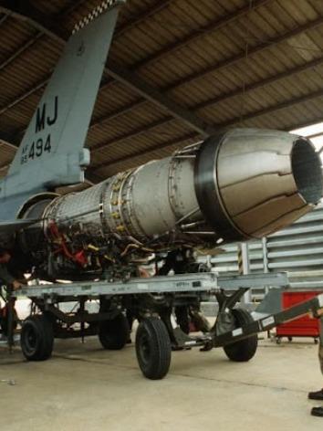
GE F110 Engine
Engine Name | General Electric F110-GE-129 | ||||||||
|---|---|---|---|---|---|---|---|---|---|
Manufacturer | General Electric Aviation | ||||||||
Engine Type | Low bypass ratio, twin-spool, afterburning turbofan engine | ||||||||
Initial Development | Late 1970s - early 1980s | ||||||||
Platforms Used | Lockheed Martin F-16C/D - Boeing F-15 - Mitsubishi F-2 | ||||||||
Thrust Values | Afterburner off: 76.3 kN - Afterburner on: 131.2 kN | ||||||||
Total Compression Ratio | 30.7 | ||||||||
Airflow Rate | 122.4 (kg/s) | ||||||||
Bypass Ratio | 0.76 | ||||||||
Dimensions | Length: 181.9 inches (4.6 m) - Diameter: 46.5 inches (1.18 m) | ||||||||
Weight (Dry) | 1805 kg | ||||||||
Thrust-to-Weight Ratio | 7.09 | ||||||||
Durability | Approximately 6,000 TAC cycles | ||||||||
General Electric F110 Turbofan Engine is a high-performance fourth-generation turbofan engine with a low bypass ratio, dual-shaft configuration, and an afterburner unit that enables high thrust output. Optimized for durability, reliability, and advanced engine control systems, it can generate up to 131.2 kN of thrust and offers extended maintenance intervals.
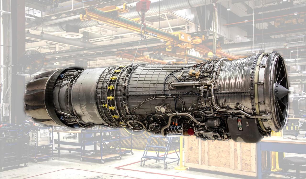
F110 Motoru (StandardAero)
The origins of the F110 engine trace back to the Alternate Fighter Engine (AFE) program initiated by the United States Air Force in the late 1970s. This program aimed to overcome operational issues with the Pratt & Whitney F100 engines and to develop a more durable, reliable, and cost-effective alternative. General Electric developed the F110 based on the F101 engine used in the B-1B bomber. The F110 was created by adding a new fan, an improved afterburner section, and an adjustable exhaust nozzle to the F101’s core.
The F110-GE-129 consists of a three-stage fan, a nine-stage high-pressure compressor, a single-stage high-pressure turbine, and a two-stage low-pressure turbine. The afterburner section and exhaust nozzle are adjustable. The blade angles of the fan and compressors are controlled by an electromechanical system based on engine speed and temperature.
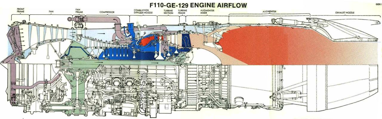
F110 Motoru Kesit Görünümü (
Engine components are manufactured from various nickel, cobalt, and titanium alloys designed to withstand high temperatures and stress conditions. The high-pressure turbine rotors are made from Rene 125, the low-pressure turbine stator from Rene 95, and the afterburner sections from IN625 alloy. These alloys provide high mechanical strength and thermal resistance.
The engine features a multi-layered fuel control system comprising a Digital Electronic Control (DEC), an Afterburner Control (AFC), and a Hydro-Mechanical Control (MEC) system. Primary control modes include Primary (PRI), Secondary (SEC), Hybrid (HYB), and Variable Stator Vane Hybrid (HYB VSV). This system ensures safe and optimized engine operation under various conditions.
The F110-GE-129 operates using a synthetic oil-based system that lubricates and cools the engine bearings, gears, and control systems. The starting system enables automatic engine ignition both on the ground and in flight and performs a restart function in case of compressor imbalance.
The engine is designed to require scheduled maintenance only after approximately 6000 Takeoff and Climb (TAC) cycles, representing a reduction of up to 40% in maintenance intervals. The Engine Monitoring System (EMS) enables real-time monitoring of operational parameters, allowing for predictive warnings and improved maintenance efficiency.
The F110-GE-129 is equipped with an ice prevention system that uses hot air bled from the fifth stage of the high-pressure compressor to prevent icing of the fan inlet guide vanes and inlet cone. This system operates in three modes: automatic, open, and closed. This feature enhances engine safety during high-altitude and low-temperature conditions.
The afterburner section features three annular flame holders and is fed by 201 fuel nozzles. Ignition of the fuel-air mixture is achieved by a single igniter. The IN625 nickel alloy used in the afterburner structure is critical for high-temperature resistance. At the engine exit, a programmable, Laval-type supersonic exhaust nozzle is provided for all modes. These nozzles can independently adjust both the throat and exit diameters via separate control programs, optimizing flight performance across varying altitudes and speeds.
The F110-GE-129 transfers torque from the high-pressure compressor shaft, via a reduction gearbox, to both the engine’s own auxiliary systems and the aircraft’s systems. This system powers components such as generators, fuel pumps, hydraulic pumps, and air starters. Auxiliary power units are mounted beneath the engine’s outer casing.
The engine lubrication system is designed to lubricate and cool bearings, supply pressurized oil to the exhaust nozzle control hydraulic pump, and lubricate gears within the hardware cabinet. The oil used is NATO O-148 or United States Air Force standard MIL-L-7808 synthetic oil. The system is configured to ensure continuous flow to all critical engine components.
The engine control system consists of electronic and hydro-mechanical subsystems. Under normal flight conditions, the DEC unit processes engine commands and transmits them to the relevant control units. In the event of a failure, control switches to the Secondary (SEC) mode and is managed by the hydro-mechanical unit. The HYB and HYB VSV modes are transitional modes where both electronic and hydro-mechanical control systems operate simultaneously. This multi-layered system is designed to ensure safe operation of single-engine fighter aircraft.
The durability of the F110-GE-129 has been validated through flight and ground tests on various platforms including the F-16 and F-14. The engine was subjected to over 5000 TAC cycles under extreme temperatures, cyclic loading, and operational stress conditions. No significant wear was observed in high-temperature components, indicating the engine can achieve its predicted service life. Tests confirmed that even after high cycle counts, the engine maintained an airflow of 270 lb/s (122.4 kg/s), low degradation rates, and stable performance values.
The F110 engine first underwent flight testing on an F-16 in 1980. During these tests, the engine was evaluated across a wide range of altitudes and speeds with various throttle movements, with no instances of stall or flameout. The reliability of the afterburner ignition system was found to be high, particularly due to the integration of the Light Off Detector (LOD) sensor. This sensor prevents excessive fuel injection until the afterburner flame is confirmed, thereby avoiding potential fan stalls caused by harsh ignitions.
The F110-GE-100 and subsequent F110-GE-129 variants underwent extensive flight testing on platforms beyond the F-16, including the F-14 and F-15. On the F-14, the engine’s higher airflow and thrust capacity delivered improved performance compared to the TF30. For the F-15, design modifications reduced the engine diameter by approximately 1.25 inches and re-packaged the control and accessory systems to ensure compatibility with the F-15 airframe, aiming for common platform usage.
The F110 engine was developed under the United States Air Force’s Engine Structural Integrity Program (ENSIP). ENSIP encompasses specific analyses, component tests, and engine tests to ensure mechanical robustness. As the F110 uses the F101 engine core, its foundational ENSIP framework is derived from the F101 program. Turbine disks operating under high temperatures and cyclic loads were re-evaluated and redesigned with mass reinforcements to ensure durability over their intended service life.
The F110-GE-129 features an advanced Engine Monitoring System (EMS) integrated with digital engine control. The EMS monitors engine parameters during flight, records fault codes, detects parameter excursions, and tracks performance trends. The system consists of components including the EMS Processor (EMSP) on the engine, the EMS Computer (EMSC) on the aircraft, and the Data Transfer Unit (DDTU) for data export. The goal of the system is to make maintenance activities data-driven, optimize scheduled maintenance intervals, and prevent unexpected failures.
The F110 engine shares approximately 81% parts commonality with the F100 and F101 engines. This enables extensive reuse of maintenance equipment and field support systems. The F110 maintenance infrastructure is largely compatible with existing F100 support hardware, allowing the engine’s entry into service without requiring major additional investments. Additionally, the engine’s line maintenance duration and man-hours per flight hour (MMH/FH) are significantly lower than those of the F100 engine.
Coalson, Michael S. Development of the F110-GE-100 Engine. ASME Paper 84-GT-132. New York: The American Society of Mechanical Engineers, 1984.
GE Aviation. F110-GE-129 Turbofan Engine – Product Datasheet. AE-44043A. Cincinnati, OH: GE Aviation, 2014.
Hocko, Marián, Martin Venceľ, Maroš Divok, and Milan Husťák. "General Electric F110-GE-129 Turbofan Engine." Acta Avionica 25, no. 2 (2023). Technical University of Košice, Slovakia.
SVPPBELLUM. "Il General Electric F110-GE-129: Il turbofan che ha dato nuova vita all’F-16." SVPPBELLUM (blog). April 2021. Accessed April 26, 2025.https://svppbellum.blogspot.com/2021/04/il-general-electric-f110-ge-129-il.html.
StandardAero. "F110." Accessed April 26, 2025.https://standardaero.com/engines/geaerospace/f110/.

GE F110 Engine
Engine Name | General Electric F110-GE-129 | ||||||||
|---|---|---|---|---|---|---|---|---|---|
Manufacturer | General Electric Aviation | ||||||||
Engine Type | Low bypass ratio, twin-spool, afterburning turbofan engine | ||||||||
Initial Development | Late 1970s - early 1980s | ||||||||
Platforms Used | Lockheed Martin F-16C/D - Boeing F-15 - Mitsubishi F-2 | ||||||||
Thrust Values | Afterburner off: 76.3 kN - Afterburner on: 131.2 kN | ||||||||
Total Compression Ratio | 30.7 | ||||||||
Airflow Rate | 122.4 (kg/s) | ||||||||
Bypass Ratio | 0.76 | ||||||||
Dimensions | Length: 181.9 inches (4.6 m) - Diameter: 46.5 inches (1.18 m) | ||||||||
Weight (Dry) | 1805 kg | ||||||||
Thrust-to-Weight Ratio | 7.09 | ||||||||
Durability | Approximately 6,000 TAC cycles | ||||||||
No Discussion Added Yet
Start discussion for "General Electric F110 Turbofan Engine" article
Development History
Structural Features and Systems
Key Technical Specifications
Materials Technology
Control and Support Systems
Lubrication and Starting Systems
Durability and Maintenance
Cooling and Ice Prevention Systems
Afterburner and Exhaust Nozzle
Auxiliary Unit Drive System and Hardware Cabinet
Engine Lubrication System
Electronic Control and Safety Systems
Durability and Test Data
Flight Tests and Platform Compatibility
Engine Structural Integrity Program (ENSIP)
Integrated Engine Monitoring System (EMS)
Logistical Compatibility and Maintenance Accessibility