badge icon

This article was automatically translated from the original Turkish version.
Article

Turboshaft Engine

Quote
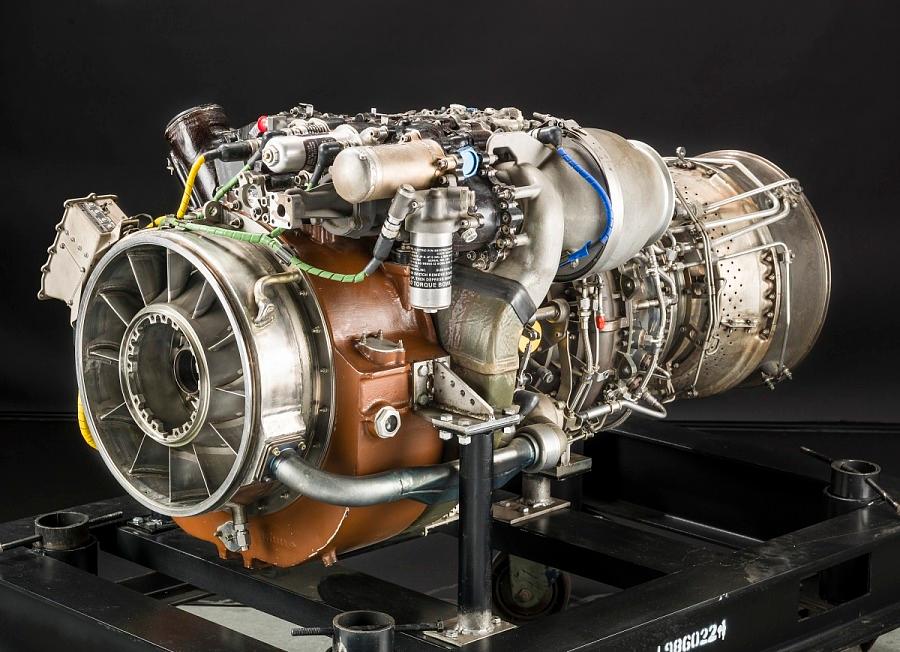
NASM-A19860224000-NASM2014-02840-000001.jpg

Turboshaft Engine

Door

Jet Engine

Initial Production Date

1940

Principle(s) of Operation

Gas Turbine

Power Output

Mechanical

Main Component

Compressor

Exhaust

Shaft

Turbine

Combustion Chamber

A turboshaft engine is a type of gas turbine engine specifically designed to produce shaft power. Its primary function is to generate mechanical power from a high-speed rotating shaft and transmit this power to external mechanical systems such as helicopter rotors or fixed generators. While thrust is the primary output in aircraft jet engines, in turboshaft engines rotational power (torque) is the primary output.

Turboshaft Engine Operating Principle

Air Inlet

The first stage of a turboshaft engine is the air inlet, which directs ambient atmospheric air into the engine in a smooth and uninterrupted manner. This inlet features an aerodynamic structure integrated into the airframe of the aircraft or helicopter and is optimized to ensure stable operation under varying altitude and speed conditions. The design objective of the air inlet is to provide a turbulent-free, laminar, and sufficiently high-volume airflow.

Functions

  1. Direct atmospheric air into the engine in a regulated manner, ensuring smooth delivery of ambient air to the compressor despite variations in flight speed and altitude.
  2. Ensure laminar and turbulence-free airflow, reducing efficiency losses and the risk of compressor stall by providing a smooth, disturbance-free flow to the compressor inlet.
  3. Minimize pressure losses, reducing pressure drops caused by friction and expansion or contraction within the air inlet duct to deliver air to the compressor at the highest possible efficiency.
  4. Provide protection against foreign object ingestion, incorporating filters, grilles, or inlet barrier systems to prevent damage from debris such as stones or dust entering the engine.
  5. Maintain stable airflow under various flight conditions, ensuring that the air inlet system continues to supply the compressor with consistent airflow even during complex maneuvers, particularly in helicopters.
  6. Provide suitable air conditions despite temperature and humidity variations, supported by anti-icing systems and other equipment to maintain engine performance under extreme hot, cold, or humid conditions.
  7. Improve acoustic performance through noise-reducing structures, contributing to noise reduction via specialized coatings in the air inlet, which is especially important in civil aviation applications.

Compressor

Compressor is one of the most critical subsystems in turboshaft engines, directly affecting overall engine efficiency, power output, and combustion quality. Its function is to mechanically compress the atmospheric air received from the air inlet, increasing its pressure and temperature to create an environment conducive to more efficient fuel-air combustion.


High-pressure air is mixed with fuel in the combustion chamber, resulting in higher combustion temperatures and greater energy release. This provides more energy to the turbine and increases the engine’s total power output. Therefore, the compressor plays a fundamental role in enabling the thermodynamic cycle of the turboshaft engine to operate efficiently. The compressor prepares air for the combustion chamber by raising its pressure. Turboshaft engines typically use axial or centrifugal compressors.

Functions

  1. Increase air pressure, the primary function of the compressor is to mechanically compress air taken at atmospheric pressure to raise its pressure, which is essential for efficient combustion in the combustion chamber.
  2. Raise air temperature, compression increases air temperature, which positively enhances combustion efficiency and enables greater energy release. However, temperature rise must be controlled, as excessive heat can negatively affect material strength and efficiency.
  3. Direct and accelerate airflow, the rotor and stator blades in the compressor guide and accelerate the airflow in a controlled manner to achieve the required flow profile at the turbine and combustion chamber inlets.
  4. Supply high-flow air, engine power is directly dependent on the mass of air entering the combustion chamber. The compressor enables high power output by providing the necessary volume of compressed air.
  5. Provide homogeneous airflow to the combustion chamber, the airflow exiting the compressor must be non-turbulent and uniform to ensure even mixing with fuel and stable, efficient combustion.
  6. Ensure stability across the engine’s operating range, the compressor must be designed to prevent stall or surge, which can disrupt airflow and cause sudden engine shutdown. Therefore, highly stable designs are critical.
  7. Adapt to varying flight conditions, turboshaft engines operate under variable conditions of altitude, temperature, and load. The compressor maintains stable air compression under these changing conditions to preserve engine reliability and performance.

Combustion Chamber

Combustion chamber is the primary source of the engine’s thrust or shaft power. Air compressed by the compressor is mixed with fuel and ignited in this chamber. The combustion of the fuel-air mixture produces gases at significantly elevated temperature and pressure. These high-energy gases are directed toward the turbine blades to convert thermal energy into mechanical energy. The combustion chamber is optimized both aerodynamically and thermally to ensure stable and efficient combustion.

Functions

  1. Create a fuel-air mixture, ensuring homogeneous mixing of compressed air from the compressor with fuel injected appropriately within the combustion chamber to establish an efficient and stable combustion environment.
  2. Ensure stable and continuous combustion, guaranteeing that the flame remains lit under varying altitude and engine load conditions to support reliable engine operation.
  3. Generate high-temperature gases, converting chemical energy into thermal energy to provide the kinetic and thermal energy required for turbine rotation.
  4. Withstand thermal stresses, requiring appropriate material selection and cooling systems to maintain structural integrity under extreme high-temperature exposure.
  5. Limit noise and emissions, necessitating specialized burners and low-emission designs to minimize sound levels and harmful gas emissions and reduce environmental impact.
  6. Direct gas flow to the turbine, ensuring smooth and controlled delivery of hot, high-pressure gases after combustion to the turbine, thereby improving energy conversion efficiency.
  7. Provide compact design with high energy density, offering an optimized structure in terms of weight and size that maximizes energy production within limited volume, enhancing overall engine performance.

Gas Turbine

The gas turbine is a critical component that converts the energy of high-temperature, high-pressure gases produced in the combustion chamber into mechanical energy. Turbine blades are rotated by the kinetic energy of these hot gases, driving both the compressor and supplying energy to the power transmission system. Typically multi-stage, each stage extracts progressively less energy from the gas stream. Turbine materials are manufactured from special alloys resistant to extreme temperatures and thermal shock. Turbine efficiency directly affects the engine’s overall fuel economy and performance. Therefore, aerodynamic design, cooling systems, and material selection are of great importance.

Functions

  1. Drive the compressor, transmitting rotational motion mechanically via the shaft to the compressor to sustain the continuous air intake and compression cycle.
  2. Generate power, converting the heat and pressure energy of combustion gases into mechanical rotational energy to produce usable power for aircraft or helicopter systems.
  3. Direct gas flow, optimizing the direction of high-velocity gases through turbine blade geometry to achieve maximum energy conversion efficiency.
  4. Withstand thermal loads, preventing turbine component damage through high-temperature-resistant materials and advanced cooling technologies.
  5. Control pressure drop, allowing high-pressure gases from the combustion chamber to expand smoothly through the turbine, minimizing energy loss.
  6. Balance rotational speed, maintaining the turbine rotor speed at levels suitable for both the compressor and the power transmission system.
  7. Operate in synchronization with the entire system, coordinating with the compressor, combustion chamber, and power output structures to enhance overall engine efficiency.

Power Transmission

Power transmission is the section that transfers the turbine’s rotational energy to mechanical systems. It typically consists of a main shaft and various gear systems. In helicopters, this system delivers energy to the main reduction gearbox that drives the rotors. In fixed-wing aircraft, it powers generators, pumps, or thrust systems. An efficient power transmission system increases engine efficiency by minimizing energy losses. This section also dampens vibrations and load imbalances to ensure safe engine operation.

Functions

  1. Transmit mechanical energy from the turbine, carrying power generation to other systems via the rotating shaft.
  2. Adjust reduction ratio, using gear systems to convert high-speed turbine rotation into appropriate torque and rotational speed for flight systems.
  3. Drive helicopter rotors, providing the correct torque and speed to the rotor system to enable flight control in helicopters.
  4. Operate generators and auxiliary equipment, supplying energy to aircraft electrical systems, hydraulic pumps, and other secondary systems.
  5. Reduce vibrations, dampening oscillations caused by shaft imbalances and sudden load changes to extend system life.
  6. Absorb excessive loads, incorporating clutch or torque-limiting mechanisms to ensure mechanical safety against sudden torque increases.
  7. Tolerate thermal expansion, featuring compensations that maintain proper alignment of components even under high-temperature conditions.

Exhaust

The exhaust section safely and efficiently discharges hot gases exiting the turbine into the atmosphere. It may also direct this gas flow to utilize residual energy for thrust generation. In jet engines, exhaust gases directly contribute to thrust; in turboshaft engines, this effect is minimal. The exhaust structure is designed to minimize aerodynamic losses. Materials are resistant to both high temperatures and corrosion. Additionally, the exhaust system helps reduce engine noise.
Functions

  1. Safely discharge hot gases, directing high-temperature gases exiting the turbine in a controlled manner to the external environment to preserve engine integrity.
  2. Minimize backpressure, enhancing engine efficiency by reducing pressure losses at the turbine outlet through optimized exhaust system design.
  3. Control noise, reducing sound intensity through integrated mufflers or diffusers in the exhaust structure to lower environmental impact.
  4. Create directed gas flow, ensuring gases exit at a specific angle and velocity to produce an airflow compatible with the aircraft’s aerodynamics.
  5. Withstand high temperatures, requiring exhaust surfaces exposed to continuous hot gas flow to resist oxidation and deformation.
  6. Support engine efficiency, positively influencing overall engine performance by reducing backflow and energy loss through optimized exhaust design.

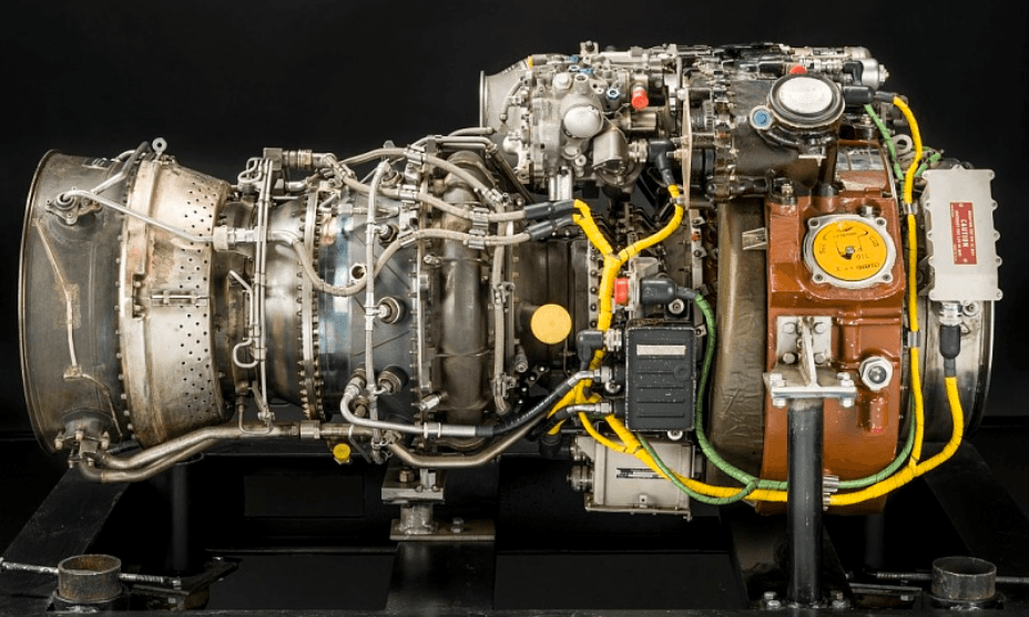
General Electric XT700-GE-700 Turboşaft Motor (airandspace.si.edu)

Applications and Technical Rationale of Turboshaft Engines

Helicopters

Turboshaft engines are widely preferred in helicopters because they deliver the high torque required to drive rotor systems with low weight.

Technical Rationale

  1. High power-to-weight ratio, which is critical for helicopters to perform vertical takeoff and landing.
  2. Compact and lightweight design, facilitating easy integration within the airframe.
  3. Output shaft compatible with reduction gearing, enabling direct torque transfer to the rotor system.
  4. Excellent load transient characteristics, providing stable performance during sudden maneuvers and variable load conditions.
  5. Stable performance across a wide altitude range, offering operational advantages in military and mountainous environments.


Gökbey (

Marine Propulsion Systems

Turboshaft engines provide ideal solutions for marine platforms with limited space and high power demands.

Technical Rationale

  1. Compact and modular design, enabling easy integration into ship engine rooms.
  2. High-speed output, allowing straightforward connection to propeller systems via gearboxes.
  3. High durability, offering long-term operation under harsh marine conditions such as saltwater exposure.
  4. Low vibration and noise, reducing acoustic signature.


LCAC-17 (ueidaq.com)

Light Armored Ground Vehicles and Tanks

Turboshaft engines are used as alternatives to piston engines in some modern tanks and armored vehicles.

Technical Rationale

  1. High acceleration capability, enabling rapid speed increases for tanks.
  2. Broad fuel compatibility, allowing operation on various fuels such as jet fuel, diesel, and kerosene.
  3. Low maintenance duration, providing logistical advantages on the battlefield.


M1 Abrams (

Bibliographies

AA. "Gökbey Helikopteri İlk Sertifikasyon Uçuşunu Yaptı." Anadolu Ajansı, 2019.https://www.aa.com.tr/tr/bilim-teknoloji/gokbey-helikopteri-ilk-sertifikasyon-ucusunu-yapti/1519149

Air and Space Museum. "General Electric XT700-GE-700 Turboshaft Engine." Smithsonian National Air and Space Museum. Accessed May 5, 2025.https://airandspace.si.edu/collection-objects/general-electric-xt700-ge-700-turboshaft-engine/nasm_A19860224000

Honeywell Aerospace. "M1 Abrams: Still Going Strong with Honeywell Jet Engine." Honeywell Aerospace, May 2023.https://aerospace.honeywell.com/us/en/about-us/blogs/m1-abrams-still-going-strong-with-honeywell-jet-engine

Kordinat Teknoloji. *Technological Competitive Analysis.* March 2021.https://kordinat.com.tr/wp-content/uploads/2021/03/TECHNOLOGIGAL-COMPETITIVE-ANALYSIS.pdf

Mechanical Jungle. "Turboshaft Engine: Introduction." Accessed May 5, 2025.

NASA. *Nacelle Inlet Icing Design Guidelines and Icing Wind Tunnel Test Techniques.* NASA Technical Memorandum TM–20230011422, April 2023.https://ntrs.nasa.gov/api/citations/20230011422/downloads/TM-20230011422.pdf

Skybrary. "Turboshaft Engine." Skybrary Aviation Safety. Accessed May 5, 2025.

UEI. "UEI LCAC SLEP." UEI Application Story. Accessed May 5, 2025.https://www.ueidaq.com/application-story-uei-lcac-slep

Author Information

Avatar
AuthorMuhammed İncelJuly 14, 2026 at 5:24 PM

Discussions

No Discussion Added Yet

Start discussion for "Turboshaft Engine" article

View Discussions

Contents

  • Turboshaft Engine Operating Principle

    • Air Inlet

      • Functions

    • Compressor

      • Functions

    • Combustion Chamber

      • Functions

    • Gas Turbine

      • Functions

    • Power Transmission

      • Functions

    • Exhaust

      • Functions

  • Applications and Technical Rationale of Turboshaft Engines

    • Helicopters

      • Technical Rationale

    • Marine Propulsion Systems

      • Technical Rationale

    • Light Armored Ground Vehicles and Tanks

      • Technical Rationale