


This article was automatically translated from the original Turkish version.
+1 More
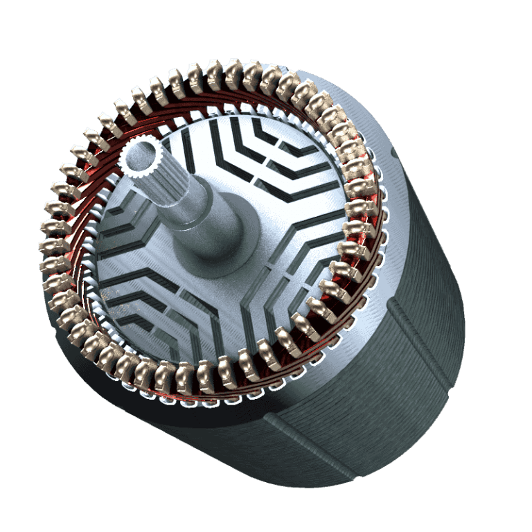
Synchronous Reluctance Motor
Electric Machine Type | Synchronous Reluctance Motor | ||||||||
|---|---|---|---|---|---|---|---|---|---|
Main Component | Stator Windings Rotor | ||||||||
Discovery | 1923 (Kostko) | ||||||||
Field of Use | electric vehicles Industrial drives pumping systems etc. automation robotics renewable energy systems | ||||||||
Synchronous reluctance motors (SynRM) are electric machines that generate torque through magnetic reluctance and operate on AC power. Unlike other electric machines, their rotors (rotating part) contain no windings; torque is produced based on the design of flux barriers within the rotor. Motor performance can be enhanced by adding permanent magnets to the rotor.
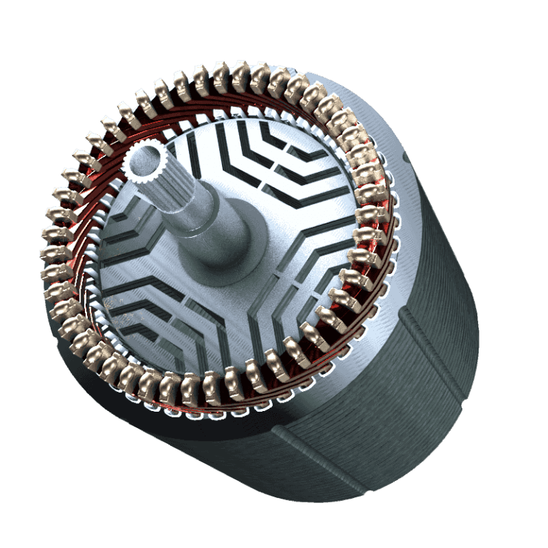
Synchronous Reluctance Motor Structure - Oswos
SynRMs are polyphase alternating current machines. Their stator (stationary part) structure is similar to that of other AC motors, but their rotor designs are more distinct and complex.
To maintain torque at maximum levels, different rotor configurations have been developed, including axial (ALA) and transverse (TLA) laminations.
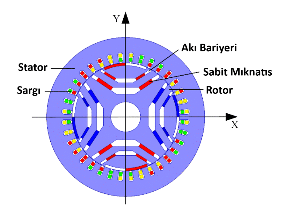
Synchronous Reluctance Motor Components -
The stator, like in other polyphase AC machines, consists of multiple phase winding groups placed in slots cut along the stator axis.
The rotor features a design known as flux barriers, which distinguish SynRMs from other AC motors and are responsible for torque generation. According to this design, the saliency ratio is defined as the ratio of magnetic flux densities along the d and q axes in the rotor coordinate system. To maximize the torque produced by the motor, the saliency ratio must be increased; therefore, rotor flux barrier designs are implemented in SynRMs.
The primary source of torque in SynRMs is reluctance torque. Reluctance is a magnetic resistance that opposes the flow of magnetic flux in a magnetic circuit and is obtained by dividing the magnetomotive force by the flux. Reluctance torque arises due to differing reluctance values along different axes in a ferromagnetic material. In a motor within a magnetic field, the rotor rotates so that its d-axis, where reluctance is low and inductance is high and magnetic flux flows easily, aligns with the magnetic field to minimize the flux path. This alignment generates reluctance torque.
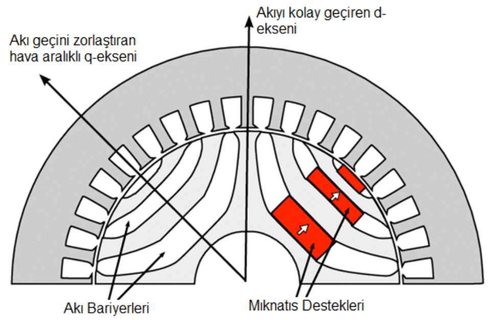
Synchronous Reluctance Motor Flux Barriers - DergiPark
SynRMs are powered by balanced polyphase (typically three-phase) AC voltage, generating a rotating magnetic field in the air gap between stator and rotor at synchronous speed. The resulting magnetic flux completes its path along the d-axis of the rotor, where reluctance is low and inductance is high, causing the rotor to rotate at synchronous speed.
Synchronous Reluctance Motor Operation Demonstration - ELIN Motoren
As the magnetic flux completes its path along the d-axis, the magnetic field in the windings continuously changes, causing the d-axis to continuously align with the rotating magnetic field, initiating rotation at synchronous speed. The torque produced by the SynRM depends on the inductance values along the d and q axes and is therefore determined by the saliency ratio. To maximize torque, the saliency ratio must be increased, as this parameter is central to machine design and optimization. To achieve maximum torque, the d-axis inductance (Ld) should be as high as possible while the q-axis inductance (Lq) should be reduced to the lowest feasible value.
SynRMs are generally driven by variable frequency inverters. Early designs included short-circuited cage structures on the rotor to assist with motor starting. However, these structures negatively affected the saliency ratio responsible for torque production and are therefore rarely used today. Currently, inverter systems enable control over both motor starting and nominal operation, maintaining constant power and constant torque regions.
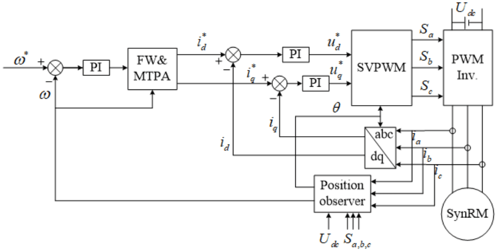
Synchronous Reluctance Motor Example Control Scheme - Veichi
Generally, maximum torque per ampere (MTPA) control strategy is employed. Under this strategy, the electrical angle between the current vector and the d-axis is maintained at 45° to produce maximum torque across varying speed and load conditions. Implementation of this control requires knowledge of rotor position and speed. The current, speed, and position data from the motor are processed mathematically to determine the required reference d- and q-axis currents. Based on these calculations, the polyphase AC power supplied to the motor stator is controlled using various semiconductor devices.
Due to their structural simplicity, robust construction, and suitability for constant-speed operation, SynRMs are used in various applications including electric vehicles, HVAC systems, industrial automation, compressors, pumps, renewable energy generation, and household appliances.
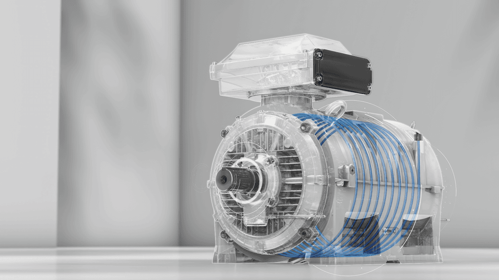
Synchronous Reluctance Motor Example Application - ABB
"Senkron relüktans motor için Açık Döngü Vektör kontrol teknolojisi - powered by empirecms." Accessed May 7, 2025.https://tr.veichi.com/e/wap/show.php?classid=177&id=130&style=0&bclassid=0&cid=76&cpage=2.
ABB. "ABB Achieves World First with Liquid-Cooled IE5 SYNRM Motor That Sets the Benchmark for Energy Efficiency and High Power Output." Accessed May 7, 2025.https://new.abb.com/news/detail/112311/abb-achieves-world-first-with-liquid-cooled-ie5-synrm-motor-that-sets-the-benchmark-for-energy-efficiency-and-high-power-output.
Balamurugan, P. N. “EE6703 SEM Unit 1 - Synchronous Reluctance Motors.” Accessed May 7, 2025.https://pnbalamurugan.yolasite.com/resources/EE6703%20SEM%20UNIT%201%20-%20SYNCHRONOUS%20RELUCTANCE%20MOTORS.pdf.
Bukhari, Syed Abid, and Vikram Kumar. "Development of a Synchronous Reluctance Motor for Industrial Application." *Sukkur IBA Journal of Emerging Technologies* 7, no. 1 (June 14, 2024): 15–23. Accessed May 7, 2025.https://doi.org/10.30537/sjet.v7i1.1461.
ELIN Motoren GmbH. "ELIN Motoren Synchronous Reluctance Motor." YouTube, November 11, 2024. Accessed May 7, 2025.https://www.youtube.com/watch?v=zvGW5wQg24s
Epaddock. "SynRM Reluctance Electric Motor." Accessed May 7, 2025.https://www.epaddock.it/en/synrm-reluctance-electric-motor/.
Ergene, T., Lale, Murat Yılmaz, Murat İmeryüz, Liridon Xheladini, Alper Tap, and Taşdemir Aşan. "Sürekli Mıknatıs Destekli Senkron Relüktans Motorlarda Mıknatıs Yerleşiminin Performansa Etkisi." EMO Bilimsel Dergi 8, no. 1 (June 2018): 19-24.
Gözüaçık, Emre, and Mehmet Akar. "Senkron Relüktans Motor Analitik Hesabı Ve Tasarımı." Gaziosmanpaşa Bilimsel Araştırma Dergisi 12, no. 1 (June 2023): 86-100.

Synchronous Reluctance Motor
Electric Machine Type | Synchronous Reluctance Motor | ||||||||
|---|---|---|---|---|---|---|---|---|---|
Main Component | Stator Windings Rotor | ||||||||
Discovery | 1923 (Kostko) | ||||||||
Field of Use | electric vehicles Industrial drives pumping systems etc. automation robotics renewable energy systems | ||||||||
No Discussion Added Yet
Start discussion for "Synchronous Reluctance Motor" article
General Construction
Operating Principle
Motor Control
Advantages
Disadvantages
Applications