


This article was automatically translated from the original Turkish version.
+1 More
The OSI (Open Systems Interconnection) model was developed by ISO (International Organization for Standardization). Its purpose is to define how communication between two computers should occur.
The first OSI models were introduced in the late 1970s and early 1980s by ISO's TC 97 (Technical Committee 97), Information Processing. The final OSI model was published in 1984. The model quickly gained acceptance and became a standard reference for network systems. This data model provides a universal language for computer networks, enabling diverse technologies to communicate using standard protocols or communication rules. Each technology at a specific layer must provide certain features and perform specific functions to be useful in network communication. Higher-layer technologies benefit from abstraction, allowing them to use lower-level technologies without needing to consider their underlying application details.
The layers of the OSI model encompass all types of network communication between software and hardware components. The model is designed to enable two independent systems to communicate via standardized interfaces or protocols based on their existing working layer.
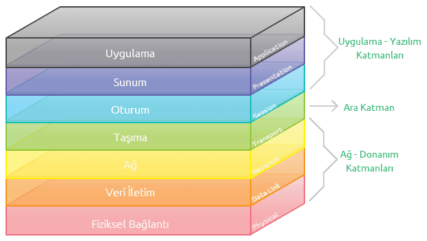
OSI layers
The Application layer provides the interface between the computer and the network. Among the OSI layers, only this layer does not provide services to other layers. It enables applications to operate over the network. Protocols and applications such as SSH, Telnet, FTP, TFTP, SMTP, SNMP, HTTP, and DNS operate at this layer.
The most important function of the Presentation layer is to format data so that it can be understood by the receiving computer. This enables different programs to use each other's data.
The Presentation layer receives data from the Application layer and then performs adjustments regarding the structure and format of the data, determining its format. Encryption, decryption, and compression of data are also handled at this layer. Formats such as GIF, JPEG, TIFF, EBCDIC, and ASCII operate at this layer.
The Session layer manages the establishment and use of connections between applications on two computers. When one computer communicates simultaneously with multiple other computers, it ensures that it can speak to the correct one as needed. This is achieved by separating data destined for the Presentation layer according to different sessions. Protocols such as NetBIOS, RPC, Named Pipes, and Sockets operate at this layer.
The Transport layer divides data received from higher layers into segments for transmission across the network. Protocols such as TCP, UDP, and SPX operate at this layer. These protocols also perform tasks such as error control.
The Network layer is the layer where information is added to indicate that a data packet must be routed to a different network. At this layer, data is recognized as packets.
The Network layer controls the most economical path for transmitting data between two stations. This layer enables data to be routed through routers. During the network phase, messages are addressed and logical addresses are converted into physical addresses. Routing of network traffic and similar operations are also performed at this stage.
The Data Link layer defines the rules for accessing and using the Physical layer. Access methods such as Ethernet or Token Ring operate at this layer. These access methods process and transmit data according to their own protocols.
Data from the Network layer is sent to the Physical layer through the Data Link layer. At this stage, data is divided into specific segments. These segments are called packets or frames. Frames are packets that ensure data is transmitted under controlled conditions.
The Data Link layer is divided into two sublayers: LLC and MAC.
The Media Access Control (MAC) sublayer packages data with error control codes and the MAC addresses of the sender and receiver, then transfers it to the Physical layer. On the receiving side, it reverses these operations and passes the data to the LLC, the second layer of the data link.
The Logical Link Control (LLC) sublayer acts as a transition layer for the Network layer above it. It creates protocol-specific logical ports (SAPs), enabling the same protocols on the source and destination machines to communicate. LLC is also responsible for retransmitting corrupted data packets. Another function of LLC is flow control, preventing the receiver from being overwhelmed by too many data packets.
The Physical layer defines the structure that data will take on the cable. Data is transmitted as bits. This layer specifies how ones and zeros are converted into and transmitted as electrical, optical, or radio signals. On the transmitting side, the Physical layer converts ones and zeros into electrical signals and places them on the cable. On the receiving side, it converts the signals read from the cable back into ones and zeros.
The Physical layer defines how data bits are transmitted to the other side via the used medium (cable, fiber optical, radio signals). For data transmission to be possible, both sides must be defined by the same rules.
A Hub operates at Layer 1. This device receives incoming data as electrical signals and repeats these signals to its other ports.

Example of a Hub
Amazon.com. "OSI modeli Nedir?" Accessed [Date]. https://aws.amazon.com/tr/what-is/osi-model/
Windows Learn. "Windows network architecture and the OSI model." https://learn.microsoft.com/tr-tr/windows-hardware/drivers/network/windows-network-architecture-and-the-osi-model
İstanbul Teknik Üniversitesi Bilgi İşlem Daire Başkanlığı. (2013). OSI Katmanları. https://bidb.itu.edu.tr/seyir-defteri/blog/2013/09/07/osi-katmanlar%C4%B1

Advantages of the OSI Model
OSI Layers
Application Layer
Presentation Layer
Session Layer
Transport Layer
Network Layer
Data Link Layer
Physical Layer