


This article was automatically translated from the original Turkish version.
An op-amp is an abbreviation of the English term "Operational Amplifier" and is called "İşlemsel Kuvvetlendirici" in Turkish. Op-amps, which are widely used in electronic circuits, amplify small input signals to produce larger output signals by virtue of their high input impedance and low output impedance. Although originally developed for applications in analog computers, today they play a vital role in signal processing filtering, oscillator design, and various control systems. Op-amps are analyzed considering both ideal and real-world characteristics.
An op-amp is typically a electronic circuit element with differential inputs and a single-ended output. It has two input terminals: the inverting input (–) and the non-inverting input (+). The output is determined by the voltage difference between these two inputs. An ideal op-amp is assumed to have infinite gain, infinite input impedance, and zero output impedance.
An op-amp circuit contains a multilayer structure composed of transistors, resistors, and capacitors. Generally, the following stages are present:
In the ideal op-amp model, the following assumptions are made:
In real op-amps, these values are finite, but ideal assumptions provide sufficient accuracy for many practical applications.
Operational amplifiers are used in a variety of applications with different circuit topologies. These applications are typically based on fundamental circuit configurations.
The inverting amplifier circuit produces an output signal with a 180-degree phase shift relative to the input signal. The gain is determined by the ratio of the feedback resistor to the input resistor.
Av = - (Rf / Rin)
Here, Rf is the feedback resistor and Rin is the input resistor.
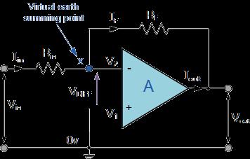
Tersleyen Kuvvetlendirici (electronics-tutorials.ws)
In the non-inverting amplifier circuit, the input signal is applied directly to the non-inverting input. In this configuration, the signal phase is preserved.
Av = 1 + (Rf / Rin)
This configuration is suitable for applications requiring high input impedance.
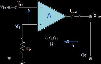
Terslemeyen Kuvvetlendirici (electronics-tutorials.ws)
The voltage follower circuit is used to transmit a signal without amplification. Its gain is 1. Due to its very high input impedance and very low output impedance, it provides circuit isolation.
An op-amp circuit used to sum multiple input signals. It is commonly used in audio engineering and data acquisition systems.
Vout = - ( (V1 * Rf / R1) + (V2 * Rf / R2) + ... + (Vn * Rf / Rn) )
Used to amplify the difference between two input signals. It is effective in noise rejection and signal processing applications.
Several important characteristics must be considered when selecting and applying op-amps:
A small current component that flows through the op-amp input terminals. It is zero in an ideal op-amp but has a finite value in real circuits.
The output voltage that appears when the input voltage difference is zero. It is ideally zero.
The product of gain and bandwidth remains constant. It becomes critical in high-frequency applications.
The rate at which the op-amp’s output voltage changes per unit time. Its unit is V/μs. It is a critical parameter for high-speed signal processing.
When designing op-amp circuits, the following considerations must be observed:
Different types of op-amps exist depending on their intended use and performance criteria.
Designed for standard applications. Models such as the LM741 belong to this category.
Used in applications where signal frequencies are very high. Examples include the AD8000.
Preferred in battery-powered devices. Models such as the MCP602 provide low power consumption.
Franco, Sergio. Design with Operational Amplifiers and Analog Integrated Circuits. McGraw-Hill, 2014.
Horowitz, Paul, and Winfield Hill. The Art of Electronics. Cambridge University Press, 2015.
Sedra, Adel S., and Kenneth C. Smith. Microelectronic Circuits. Oxford University Press, 2016.

No Discussion Added Yet
Start discussion for "Op-amp (Operational Amplifier)" article
Structure and Basic Characteristics of the Op-amp
Basic Structure
Applications of Op-amp Circuits
Inverting Amplifier
Gain formula:
Non-Inverting Amplifier
Gain formula:
Voltage Follower (Buffer)
Summing Amplifier
Output formula:
Differential Amplifier
Op-amp Characteristics
Input Bias Current
Offset Voltage
Gain Bandwidth Product
Slew Rate
Important Considerations in Applications
Types of Op-amps
General Purpose Op-amps
High-Speed Op-amps
Low Power Consumption Op-amps