


This article was automatically translated from the original Turkish version.
+1 More
Multilevel Inverter (Generated by Artificial Intelligence)
Area | Power Electronics | ||||||||
|---|---|---|---|---|---|---|---|---|---|
Application Area | HVDC transmission UPS Electric vehicles Photovoltaic systems Motor drives | ||||||||
Fundamental Topologies | Diode-Clamped (NPC), Flying Capacitor (FC), Cascaded H-Bridge (CHB), Hybrid Structures | ||||||||
Modulation Methods | Carrier-Based PWM, Selective Harmonic Elimination, Space Vector Modulation | ||||||||
Control Methods | Model Predictive Control (MPC) Capacitor voltage balancing algorithms Grid synchronization with PLL Double-loop control (current-voltage) PI and PR Controller | ||||||||
Use in Solar Energy Applications | Integrated DC voltage control with MPPT, PR-controlled output current regulation, PLL for grid phase alignment, reactive power control and harmonic suppression | ||||||||
Advantage | Direct use in medium and high voltage Low harmonic distortion High efficiency Modular structure | ||||||||
Difficulty | Capacitor voltage balancing requirement Complexity of control algorithms Increasing number of components (especially for high levels) | ||||||||
Multilevel inverters (MLI) are power electronics converters that transform electrical energy from a direct current (DC) source into alternating current (AC) at multiple output voltage levels. These structures have been developed to reduce harmonic content in the output waveform, limit voltage stress on switching components, and improve energy efficiency in high-voltage and high-power applications. They are widely used in renewable energy systems, HVDC transmission, motor drives, and electric vehicle technologies.
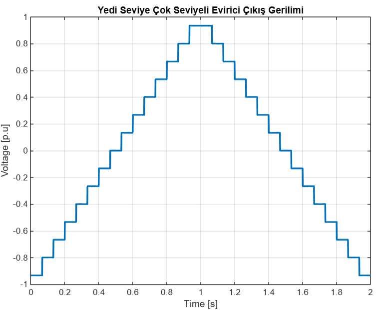
Yedi Seviye Çok Seviyeli Evirici Çıkış Gerilimi Gösterimi
The first multilevel inverter topology was introduced in 1975 and gained broader application in the 1980s with the adoption of diode-clamped topologies. Subsequent years saw the development of flying capacitor and cascaded H-bridge topologies. Starting in the 2000s, increasing demands for modularity, harmonic reduction, and efficiency led to the integration of advanced control techniques into these structures. Today, multilevel inverters serve as fundamental power conversion units in applications ranging from grid-connected solar energy systems to electric vehicle propulsion systems.
The Neutral Point Clamped (NPC) topology connects each phase leg to different voltage levels through clamp diodes placed between capacitors connected to the DC link. The three-level NPC structure is widely used in industry. Achieving four or more levels is limited by the increased number of diodes and the challenge of balancing capacitor voltages. This topology is typically preferred in medium-voltage motor drives.
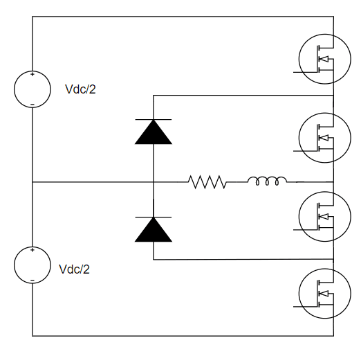
Tek-Faz Üç Seviye Diyot-Kenetli Evirici Topolojisi
In the Flying Capacitor (FC) topology, each phase leg generates multilevel output using flying capacitors. This structure operates without clamp diodes and allows balancing of capacitor voltages through phase-internal switching redundancy. However, the initial charging process and regulation of capacitor voltages increase application complexity.
The CHB topology consists of H-bridge cells connected in series, each powered by an independent DC source. Its modular structure enables individual control of each cell and provides strong harmonic suppression capability, making it particularly suitable for photovoltaic (PV) applications. Symmetric configurations use equal DC voltages across all cells, while asymmetric configurations achieve higher output levels with fewer cells by using different voltage levels.
In hybrid topologies, different multilevel structures are combined. For example, the high-voltage stage of a phase leg may use an NPC configuration while the low-voltage stage employs a CHB structure. This approach reduces cost and system complexity by decreasing the number of switching components. Reduced Device Count (RDC) topologies offer simplified configurations for the same purpose.
In carrier-based PWM techniques, a sinusoidal reference signal is compared with N-1 triangular carrier signals. This method offers advantages such as fixed switching frequency and easy integration with digital controllers. The most common variants are:
SHE optimizes switching angles to eliminate specific harmonics from the output. Using Fourier series analysis, this method sets the amplitude of targeted harmonics to zero and is especially effective in high-power, low-switching-frequency systems. However, real-time control is challenging.
SVM involves transforming three-phase systems into a two-dimensional vector plane and selecting optimal switching vectors. It offers high harmonic suppression performance and more efficient DC voltage utilization. However, its application to multilevel systems is complex.
PI (Proportional-Integral) controllers generate system response using the integral of the error signal and are the fundamental controllers for voltage and current regulation. PR (Proportional-Resonant) controllers provide zero steady-state error for AC reference signals; their resonant structure effectively suppresses errors at specific frequencies.
This method consists of an inner current loop and an outer voltage loop. The inner loop regulates the output current while the outer loop monitors the DC link voltage or grid voltage. This structure enhances system stability and improves adaptation to dynamic conditions.
In grid-connected photovoltaic systems, control of multilevel inverters is critical for both power quality and energy management. The following control structures are commonly used in such applications:
To maximize the output power of the Maximum Power Point Tracking (MPPT) algorithm is applied (e.g., Perturb and Observe). The reference voltage determined by MPPT is fed to the DC link voltage loop. The output current is compared with a grid-synchronized reference and tracked using a PR-type inner current controller.
The output current must be phase-aligned with the grid voltage. For this purpose, a Phase Locked Loop (PLL) is used to track grid frequency and phase. This enables active power delivery to the grid and allows reactive power control.
Harmonics originating from the multilevel structure are suppressed via PR controllers. Simultaneously, the phase of the current injected into the grid is adjusted to maintain the power factor close to unity or to provide reactive power as required by the user.
Malinowski, Mariusz, Konstantinos Gopakumar, José Rodríguez, and Marcelo Pérez. “A Survey on Cascaded Multilevel Inverters.” *IEEE Transactions on Industrial Electronics* 57, no. 7 (2010): 2197–2206.https://doi.org/10.1109/TIE.2009.2030767
Ojo, Olatunji, and Srikanth Peram. “Chapter 3: Operation and Topologies of Multilevel Converters.” In *Power Electronics Course Notes*. Tennessee Technological University, 2023.https://www.tntech.edu/engineering/pdf/cesr/ojo/srikanth/chapter_3.pdf
Rodríguez, José, Jih-Sheng Lai, and Fang Zheng Peng. “Multilevel Inverters: A Survey of Topologies, Controls, and Applications.” *IEEE Transactions on Industrial Electronics* 49, no. 4 (August 2002): 724–738.https://doi.org/10.1109/TIE.2002.801052.
Sharma, Neha, Ankur Sharma, and Shailendra Jain. “A Comprehensive Review of Multilevel Inverters, Modulation, and Control for Grid-Interfaced Solar PV Systems.” *Scientific Reports* 14 (2024): Article no. 84296.https://doi.org/10.1038/s41598-024-84296-1

Multilevel Inverter (Generated by Artificial Intelligence)
Area | Power Electronics | ||||||||
|---|---|---|---|---|---|---|---|---|---|
Application Area | HVDC transmission UPS Electric vehicles Photovoltaic systems Motor drives | ||||||||
Fundamental Topologies | Diode-Clamped (NPC), Flying Capacitor (FC), Cascaded H-Bridge (CHB), Hybrid Structures | ||||||||
Modulation Methods | Carrier-Based PWM, Selective Harmonic Elimination, Space Vector Modulation | ||||||||
Control Methods | Model Predictive Control (MPC) Capacitor voltage balancing algorithms Grid synchronization with PLL Double-loop control (current-voltage) PI and PR Controller | ||||||||
Use in Solar Energy Applications | Integrated DC voltage control with MPPT, PR-controlled output current regulation, PLL for grid phase alignment, reactive power control and harmonic suppression | ||||||||
Advantage | Direct use in medium and high voltage Low harmonic distortion High efficiency Modular structure | ||||||||
Difficulty | Capacitor voltage balancing requirement Complexity of control algorithms Increasing number of components (especially for high levels) | ||||||||
No Discussion Added Yet
Start discussion for "Multilevel Inverters" article
Historical Development
Main Topologies
Neutral Point Clamped Inverter (NPC)
Flying Capacitor Inverter (FC)
Cascaded H-Bridge Inverter (CHB)
Hybrid and Reduced Device Count Topologies
Modulation Techniques
Carrier-Based PWM
Selective Harmonic Elimination (SHE-PWM)
Space Vector Modulation (SVM)
Control Techniques
PI and PR Controllers
Double Loop Control
Control Schemes Specific to Solar Energy Systems
MPPT-Integrated Double Loop Control
Grid Synchronization
Harmonic Suppression and Power Factor Control
Comparison of Topologies
1. Neutral Point Clamped Inverter (NPC):
2. Flying Capacitor Inverter (FC):
3. Cascaded H-Bridge Inverter (CHB):
4. Hybrid and Reduced Device Count Topologies: