


This article was automatically translated from the original Turkish version.
The eye diagram is a fundamental tool used in digital communication systems to evaluate signal integrity. This diagram consists of multiple superimposed signal waveforms displayed on an oscilloscope and derives its name from the resemblance of the resulting pattern to a human eye. Eye diagrams provide engineers with a rapid and visual means to analyze signal quality, enabling easy detection of signal distortions, noise, jitter, and other integrity issues.
Key components of an eye diagram include eye height (vertical opening) and eye width (horizontal opening). Eye height represents the voltage difference between the logical 1 and logical 0 levels. A larger eye height indicates that the signal is more resistant to noise. Eye width, on the other hand, represents the duration during which the signal remains in a valid state, and a wider eye indicates greater tolerance to timing errors.
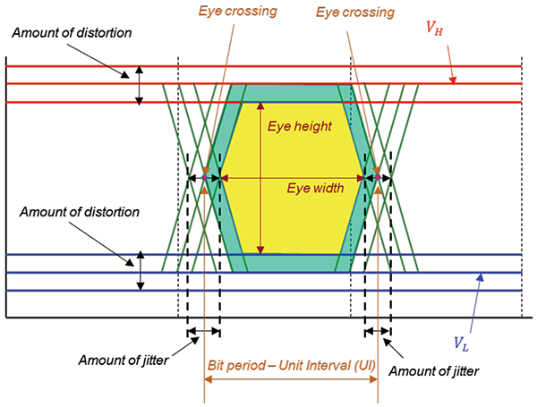
Göz Diyagramı Parametreleri (In Compliance)
Jitter refers to deviations in signal timing and appears in the eye diagram as horizontal spread. Excessive jitter can make signal detection difficult and lead to communication errors. Another important parameter, noise margin, is the distance between the edges of the eye and the maximum or minimum voltage levels. A larger noise margin implies that the signal is less affected by noise.
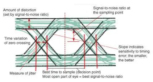
Göz Diyagramı Üzerinde Jitter Gösterimi (EDN)
Eye diagrams are also used in compliance testing against industry standards. Templates known as eye masks define acceptable signal boundaries. For example, standards such as IEEE 802.3 specify eye mask requirements for Ethernet connections. These tests are critical for verifying component performance and ensuring system reliability.
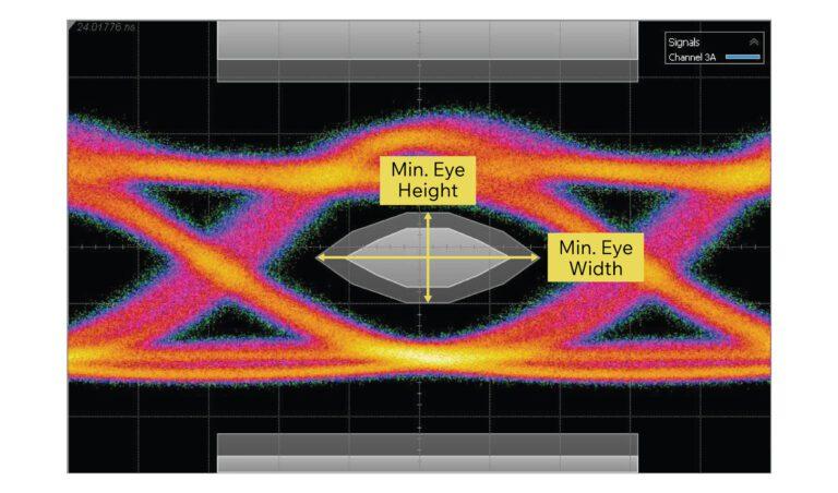
Sinyale Maske Uygulaması Örneği (ConnectorSupplier)
The applications of eye diagrams differ between optical and electrical systems. For instance, in optical transceivers, distortions occurring during the conversion of electrical signals to optical signals are assessed. In electrical interconnects, effects such as attenuation or crosstalk experienced by the signal as it passes through a connector are analyzed.
In high-speed digital systems, generating eye diagrams can be time-consuming. To accelerate this process, methods such as statistical eye diagrams have been developed. These methods calculate the signal’s probability distribution to enable more efficient analysis. Additionally, techniques such as equalizers are employed to improve eye diagram quality. For example, a decision feedback equalizer can enhance eye opening by reducing interference effects.
Eye diagrams not only assess the performance of existing systems but also play a vital role in optimizing new designs. Engineers can compare the impact of different components on signal integrity using eye diagrams and base design improvements on these results. Especially today, as data rates continue to increase, the importance of eye diagrams is growing.
Analysis of eye diagrams can be supported by other metrics such as bit error rate (BER). BER measures the error performance of a communication channel and quantitatively expresses the impact of distortions observed in the eye diagram on system performance. Therefore, combining eye diagram analysis with BER measurements enables a more comprehensive evaluation of overall system performance.
In the broadest sense, eye diagrams are an indispensable part of digital communication systems. Thanks to their multifunctional roles in visualizing signal integrity, diagnosing problems, and optimizing performance, they play a critical role in ensuring the reliability of high-speed data transmission.
Behera, Deepak, Sumit Varshney, Sunaina Srivastava, and Swapnil Tiwari. “Eye Diagram Basics: Reading, Analyzing and Applying.” EDN Network. December 16, 2011. Accessed April 23, 2025.https://www.edn.com/eye-diagram-basics-reading-and-applying-eye-diagrams/
Brower, Grover. “How to Read an Eye Diagram: Eye Diagrams in Digital Communications.” *Connector Supplier*. October 22, 2024. Accessed April, 2025.https://connectorsupplier.com/the-role-of-eye-diagrams-in-digital-communications/.
Herres, David. “The Eye Diagram: What Is It and Why Is It Used?” Test & Measurement Tips. August 16, 2016. Accessed April 23, 2025.https://www.testandmeasurementtips.com/basics-eye-diagrams/
In Compliance Magazine. "Eye Diagram – Part 1." Accessed April 23, 2025.https://incompliancemag.com/eye-diagram-part1/.
