


This article was automatically translated from the original Turkish version.
+1 More
Buck Converter
Power Electronics | Buck Converter | ||||||||
|---|---|---|---|---|---|---|---|---|---|
A buck converter is a DC-DC converter topology used to obtain a constant output voltage by stepping down the input voltage. This converter efficiently transforms energy using switching elements (typically MOSFETs), an inductor, a diode, and a capacitor. The operation principle relies on the periodic switching of the switching element to store and release energy in a controlled manner.
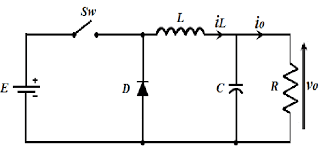
Buck converters consist of a single switching element (typically a MOSFET), a capacitor, an inductor, a diode, and a load. The buck converter circuit is shown in Figure 1.
The switch is one of the most important components in a buck converter. During operation, the switching action enables energy to be stored in the inductor and then transferred to the output. The switch is typically implemented using semiconductor devices such as MOSFET (Metal-Oxide-Semiconductor Field-Effect Transistor) or IGBT (Insulated Gate Bipolar Transistor).
The inductor is the energy storage element of the buck converter. When the switch is on, the inductor stores energy; when the switch is off, it releases this energy to the output, maintaining a constant output voltage. The inductor also reduces current ripple. In high-frequency buck converters, the inductor must have a high inductance value to minimize output current ripple.
The diode allows the energy stored in the inductor to flow to the output when the switch is off. It permits current flow in the forward direction while blocking reverse current. In buck converters, the diode’s role is to facilitate the release and transfer of the inductor’s magnetic energy to the output. Proper selection of this diode directly affects efficiency.
The capacitor is used in buck converters to smooth the output voltage. The capacitor connected at the output reduces voltage ripple and ensures a stable output voltage. During load variations, the capacitor stores and releases energy to regulate the output voltage. This component improves system efficiency and minimizes unwanted fluctuations.
The load of a buck converter is the electronic device or system connected to the output. It represents the device powered by the output voltage. As the load increases, its effect on the output voltage becomes more pronounced; therefore, buck converters are typically designed to remain stable under varying load conditions.
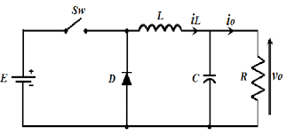
Figure 1. Buck Converter (Source: ResearchGate)
1) Switch ON: The input voltage is directly applied to the inductor, which stores energy in its magnetic field. During this phase, current increases over time. The capacitor prevents output voltage ripple and maintains a steady voltage. At the same time, the diode is reverse-biased and remains off. This stage is critical for energy storage and regulation before transfer to the output. The circuit during switch-on mode is shown in Figure 2.
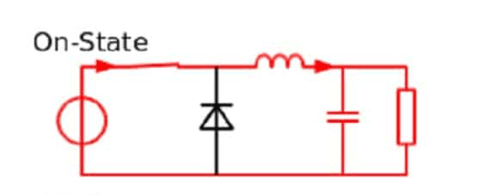
Figure 2. Buck Converter in Conduction Mode. (Source: Mühendis Beyinler)
2) Switch OFF: The energy stored in the inductor is transferred to the output through the diode. As the inductor releases its stored energy, it supplies current to the output, causing the current to decrease. The diode conducts in the forward direction to transfer energy to the output. During this phase, the capacitor maintains a smooth output voltage and stabilizes the output against load variations. This stage ensures efficient energy delivery to the load and enables the buck converter to operate effectively. The circuit during switch-off mode is shown in Figure 3.
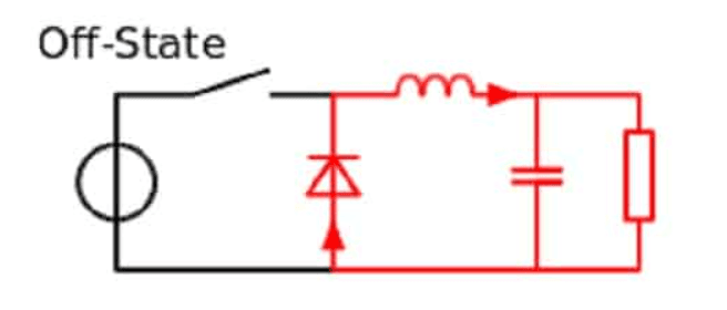
Figure 3. Buck Converter in Non-Conduction Mode. (Source: Mühendis Beyinler)
Buck converters are commonly used in systems requiring low output voltages. Applications include power supplies, battery chargers, electronic devices, and motor drivers. Due to their high efficiency and simple structure, this topology is widely preferred in power electronics systems.
Erickson, Robert W., and Dragan Maksimović. Fundamentals of Power Electronics. 2nd ed. Boston: Springer, 2001.
Lee, Fred C., and Qiang Li. "High-Frequency Integrated Point-of-Load Converters: Overview." IEEE Transactions on Power Electronics 28, no. 9 (2013): 4127–4136.
Mohan, Ned, Tore M. Undeland, and William P. Robbins. Power Electronics: Converters, Applications, and Design. 3rd ed. Hoboken, NJ: John Wiley & Sons, 2003.

Buck Converter
Power Electronics | Buck Converter | ||||||||
|---|---|---|---|---|---|---|---|---|---|
Buck Converter Topology
1. Switching Element (MOSFET or IGBT)
2. Inductor
3. Diode
4. Capacitor
5. Load
Buck Converter Operating Modes
Applications