


This article was automatically translated from the original Turkish version.
+1 More
Atmospheric re-entry, refers to the complex interplay of aerothermodynamic, structural, and kinetic effects that occur when a spacecraft enters Earth’s atmosphere at orbital velocity. During re-entry, the vehicle experiences high heat fluxes, aerodynamic loads, and dynamic pressures. Consequently, re-entry technologies encompass multidisciplinary design optimizations aimed at reducing the spacecraft’s speed, managing thermal loads, preserving structural integrity, and ensuring controlled motion toward the intended landing point.
The re-entry phenomenon is critical not only for crewed missions but also for the return processes of uncrewed systems such as satellites, space debris, and payload capsules. Objects in low Earth orbit (LEO) have limited operational lifetimes due to atmospheric drag; thus, most re-enter the atmosphere uncontrollably, with some large fragments potentially reaching the Earth’s surface. This poses a serious hazard due to the risk of impact in populated areas, necessitating national and international regulations.
Re-entry analyses require the integrated treatment of aerothermodynamic solutions, trajectory predictions, and heat load calculations. Gas kinetics, ionization, and thermochemical reactions occurring on the shock wave formed over the vehicle’s heated surfaces must be modeled alongside convective and radiative heat transfer. Solutions such as the Fay–Riddell correlation are used to estimate heat flux at the stagnation point, while CFD-supported aerodynamic analyses define surface pressure, temperature distribution, and shock configuration.
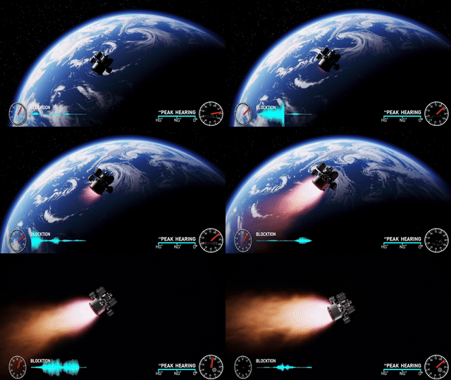
Depiction of a spacecraft returning to Earth (Generated by artificial intelligence.)
The process of atmospheric re-entry can be categorized based on the methods employed and the vehicle’s characteristics. Re-entry types are primarily determined by criteria such as the level of aerodynamic control, payload capacity, maneuverability, and the presence or absence of propulsion systems. Based on available sources, three main re-entry types can be defined.
Ballistic re-entry is a passive, uncontrolled form of atmospheric entry. The vehicle has no control surfaces or lifting geometry; the entry process is governed entirely by gravity and atmospheric drag. As a result, ballistic re-entry occurs at steep angles and subjects the vehicle to high g-forces.
This type of re-entry is common for intercontinental ballistic missiles (ICBMs) carrying nuclear warheads, derelict satellites, and passive return capsules. Heat loads during such entries are estimated using models like the Fay–Riddell correlation, and ablative thermal protection systems (TPS) are typically employed.
Mathematical modeling: Orbital equations for ballistic re-entry systems are generally modeled using three degrees of freedom (3 DOF):
Here, V is velocity, is flight path angle, D is drag force, L is lift force, r is altitude, m is mass, and g is gravitational acceleration. Additionally, the drag force is given by:
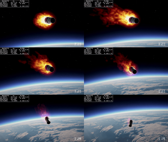
Depiction of Ballistic Re-entry (Generated by artificial intelligence.)
In lifting-body re-entry, the vehicle’s aerodynamic configuration generates lift, enabling a gentler atmospheric entry. The primary advantage of such a design is its ability to maneuver and reduce g-forces.
Modern spacecraft such as the Space Shuttle, HL-20, and Dream Chaser exemplify this type. Entry angles are optimized to distribute heat loads and precisely target the landing point. Aerodynamic control surfaces enhance maneuverability within a narrow corridor known as the re-entry corridor. Designing such vehicles requires multi-level optimization procedures and CFD-supported analyses.
Mathematical modeling: Lift force, by controlling the flight path angle, enables deceleration along the trajectory. The equations are:
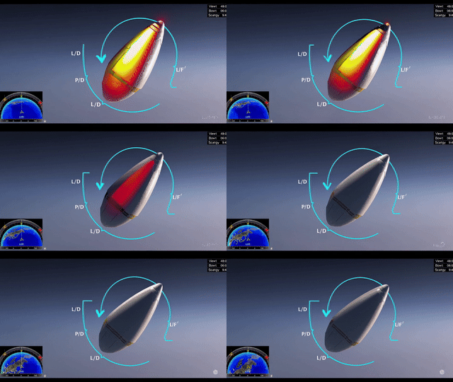
Depiction of Lifting-Body Re-entry (Generated by artificial intelligence.)
SRP is a re-entry technology developed especially for reusable rockets. In this technique, engines integrated into the vehicle’s body fire in reverse during atmospheric entry, providing counter-thrust. This slows the vehicle and helps control the shock wave structure.
SpaceX Starship and Falcon 9 are examples equipped with this technology. One key effect of SRP is the redistribution of heat loads at the vehicle’s base and the reduction of aerodynamic disturbances. However, these systems require high computational power and CFD/LES/RANS-based flow analyses.
SRP simulations have shown that plume interactions, shock structure, and final heat distribution are particularly critical at altitudes between 40 and 55 km. This demonstrates that SRP not only decelerates the vehicle but also contributes to structural integrity and heat load control.
Mathematical modeling: In retro-propulsion systems, an additional thrust term is added to the total acceleration equation:
Here, TS represents the thrust applied in the reverse direction. Plume-flow interactions and shock mitigation effects are modeled separately using CFD.
In SRP systems, the following phenomena are also present:
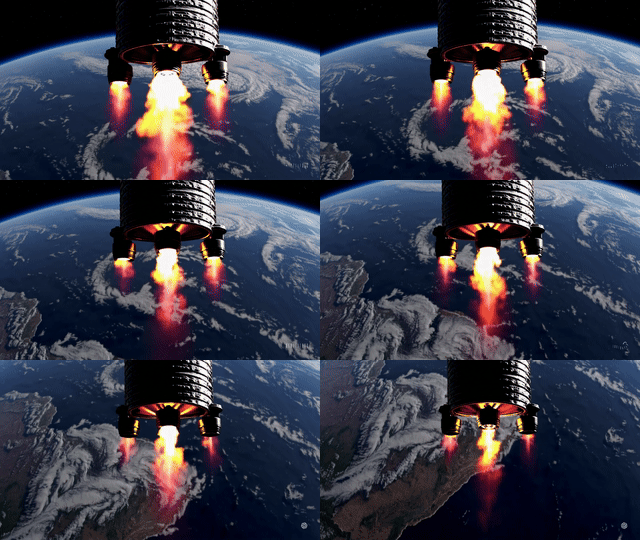
Depiction of Supersonic Retro-Propulsion (SRP) Supported Re-entry (Generated by artificial intelligence.)
The thermal environment encountered during atmospheric re-entry is one of the most critical engineering challenges for spacecraft survival. At hypersonic speeds (7–11 km/s), collisions between atmospheric molecules and the vehicle convert kinetic energy into a sudden temperature rise, followed by a strong shock wave. This creates a high-temperature region known as the shock layer, where heat transfer involves both convective and radiative components.
Thermal load is determined by pre- and post-shock gas temperatures, flow density, and vehicle geometry. Total heat flux qtotal consists of two primary components:
qtotal = qconvective + qradiative
The Fay–Riddell correlation is frequently used to estimate heat flux at the stagnation point:
Where:
Heat flux typically ranges between 200 and 3000 kW/m², with short-term peak values potentially much higher.
At high speeds and altitudes, ionized gases (plasma) formed in the shock layer emit energy via radiation under non-equilibrium conditions. This radiation is especially intense between 40 and 70 km. Radiative heat flux becomes significant at high entry velocities and low atmospheric densities. For this radiative effect:
the Stefan–Boltzmann equation is applied.
During re-entry, the vehicle passes through three primary flow regimes:
Each of these transitions directly affects the distribution of heat flux and the computational methods used.
In hypersonic wind tunnel tests (H2K) conducted by DLR, measurements on 25 mm diameter spherical probes showed heat flux values deviating by less than 16% from theoretical Fay–Riddell predictions. This validation reinforces the reliability of correlations applied to the forebody of re-entry vehicles.
In retro-propulsion systems (SRP), significant heat accumulation is observed in the plume region due to interaction between hot exhaust gases and the upstream flow. CFD-based studies have determined that maximum temperatures in this region increase by 7–8% due to afterburning effects, and heat flux on side walls can rise by up to 80% at lower altitudes (~40 km).
Thermal protection systems (TPS) capable of withstanding high temperatures are classified as ablative (Apollo), regenerative (rocket nozzle), and ceramic coating (Space Shuttle). In regions of high radiative flux, carbon-carbon or C/SiC-based panels are typically preferred.
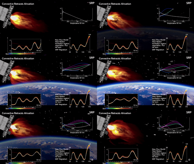
Depiction of changing heat flux, flow regime, temperature, and SRP effects during re-entry (Generated by artificial intelligence.)
Due to the severe thermal loads experienced during atmospheric re-entry, thermal protection systems (TPS) play a critical role in preserving structural integrity and maintaining safe internal temperatures. TPS not only manages the total heat flux reaching the surface but also performs effectively against convective and radiative components under varying flow regimes.
The objectives of TPS systems are:
Key parameters determining TPS selection include:
Ablative TPS systems absorb heat through controlled vaporization or chemical decomposition of the surface material. The material removes thermal energy via both chemical reactions and mass loss.
Application examples: Apollo, Orion capsules.
Materials: Phenolic resin carbon, PICA (Phenolic Impregnated Carbon Ablator), AVCOAT.
Thermal behavior:
qabsorbed = abl * qm + qconductive
Advantage: Effective under high heat loads.
Limitation: Single-use only; surface material is consumed.
This TPS type circulates a coolant in liquid or gaseous form beneath the surface. It is commonly used in rocket nozzle walls.
Application examples: Rocket motor nozzle cooling channels.
Model:
qconv = h * (Twall - Tcoolant)
These systems require complex pumping and heat exchanger systems due to their active nature.
Surface temperature rise is tolerated using ceramic or composite materials with high melting points. Energy is dissipated from the surface via radiation.
Application examples: Space Shuttle tiles, X-37B, EXPERT (ESA).
Materials: RCC (Reinforced Carbon–Carbon), C/SiC, boron carbide, zirconia ceramics.
Radiative balance:
qrad = *
Advantages: High-temperature resistance and reusability.
Limitations: Brittleness and cost.
In supersonic retro-propulsion (SRP) applications, TPS requirements differ from classical regimes. High-temperature plumes and afterburning reactions occur where SRP motor exhaust interacts with the free stream, particularly in the base region (aft-body).
Observations:
In this context, TPS design must be optimized not only for aerodynamic flow but also for interaction with jet plumes.
Both wind tunnel tests and numerical simulations are used to validate TPS systems. For example, in H2K hypersonic wind tunnel tests, the convective heat flux response of TPS materials remained within 15% of theoretical predictions.
Additionally, LES (Large Eddy Simulation), RANS (Reynolds Averaged Navier-Stokes), and chemical reaction simulations are employed for detailed TPS analysis.
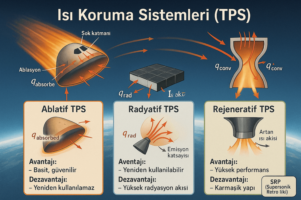
Generated by artificial intelligence.
The intense aerodynamic loads and thermal environments encountered during re-entry require optimization not only of the external geometry but also of internal structural components. In this context, aerodynamic shape, plasma-flow interactions, and material-mechanical compatibility must be addressed jointly. Re-entry success depends on the vehicle’s ability to withstand environmental loads and perform precise maneuvers according to mission profiles.
The shock wave formed ahead of a vehicle entering the atmosphere at high speed is shaped by its geometry. Blunt-body (blunt nose) geometries reduce thermal loads by distancing the shock wave from the surface. Lifting-body designs emphasize maneuverability and precise landing accuracy.
Common geometries used:
To determine aerodynamic behavior under high-temperature effects, Navier–Stokes-based solutions are required. In re-entry scenarios involving plasma and extreme temperatures, non-equilibrium chemical effects must also be considered.
The primary numerical methods used for aerodynamic analysis of re-entry vehicles are:
Example application: In configurations with SRP, interactions between motor plumes and the free stream affect both lift and drag. In such cases, nozzle placement (central or eccentric) directly alters aerodynamic moments. Simulations have analyzed aerodynamic performance using 22-nozzle configurations with different retro-propulsion combinations (Mod A, B, C).
Key outputs:
Aerodynamic shape affects not only flow dynamics but also the distribution of internal structural loads. Under high dynamic pressure, temperature differences between the surface and internal structure generate thermal stresses.
Structural optimization elements:
Material approach: Structures such as EXPERT are optimized for different load regimes using C/SiC at the nose, PM1000 on side panels, and ceramic alloy composites on wing surfaces.
The integrated optimization of aerodynamics, heat transfer, and structural mechanics enhances system-level performance of re-entry vehicles.
MDO components:
Such analyses employ genetic algorithms, parametric modeling, and bidirectional structure-flow coupling.
The re-entry process of spacecraft is directly linked not only to aerodynamic conditions but also to precise trajectory propagation techniques. Accurate prediction of re-entry timing and location requires high-sensitivity analysis of both atmospheric conditions and orbital data. The primary data source used in this process is publicly available Two-Line Element (TLE) sets. Although TLEs have low accuracy, they can be transformed into high-precision re-entry predictions using appropriate filtering and parametric estimation techniques.
TLE data is provided by the U.S. Space Command (USSTRATCOM) and is designed for use with SGP4/SDP4 orbit propagation models. These models account only for dominant orbital perturbations (J2–J5 gravitational harmonics, atmospheric drag, solar and lunar gravity, solar radiation pressure).
However, this limited modeling can lead to significant errors during the final stages of re-entry due to atmospheric density variations and inconsistent TLEs. Consequently, advanced prediction systems require statistical filtering of TLEs and re-estimation of physical parameters such as ballistic coefficient (BC).
To improve re-entry prediction accuracy, TLE datasets are filtered through the following steps:
These procedures are performed using robust statistical methods such as Theil–Sen–Siegel regression analysis.
TLEs do not directly provide physical ballistic coefficient (BC) values. However, the BC value, rescaled from the B* coefficient for use in more accurate propagation tools, is derived using the following equation:
The BC is defined as:
where:
Similarly, the SRP coefficient (SRPC), representing sensitivity to solar radiation pressure, is derived as:
Estimating these parameters is critical for transitioning from TLE-based data to physical modeling.
High-accuracy numerical propagators used to improve prediction reliability incorporate more sophisticated force models. Notably:
Main factors affecting re-entry prediction errors include:
To mitigate these uncertainties, simulations employ 6-DOF (six degrees of freedom) system models and probabilistic scenarios. For instance, the RSTT system generates a separate safety template for each possible fragmentation scenario, presenting results as map-based statistical risk outputs.
Atmospheric re-entry involves not only engineering considerations but also operational and strategic safety dimensions. Uncontrolled re-entries of satellites, rocket stages, and sample capsules pose physical threats capable of causing casualties and property damage if they impact populated areas. Therefore, risk analysis must answer not only “Did it re-enter?” but also “Where, how, and with what level of hazard?”
Key risk factors include:
The generally accepted risk threshold is:
Pcasualty < 1 x 10⁻⁴ (1 in 10,000)
That is, the probability of any fragment from re-entry causing human casualties must not exceed 1 in 10,000. This threshold is accepted by ESA, NASA, and the Australian Space Agency as an upper limit.
Most spacecraft entering the atmosphere at high speed undergo structural failure at a certain altitude. This event is termed “aerodynamic break-up.” It typically occurs when one of the following thresholds is exceeded:
Each fragment resulting from this breakup requires separate thermal and ballistic analysis. Whether fragments survive to reach the surface depends on material composition, mass, shape, and orientation. Typically, steel engine components, titanium alloy tanks, and thick structural parts can withstand atmospheric entry.
The RSTT (Range Safety Template Toolkit) system, developed by Australia’s Defence Science and Technology Organisation, offers a fractal-based approach beyond classical fragmentation models.
Model principle:
This method provides more realistic and probabilistic predictions than traditional “fixed fragment count” models.
The casualty area defines the region where a fragment poses a potential hazard upon ground impact. It typically ranges from 5 to 30 m². Larger, harder, and flatter fragments threaten wider areas.
Example: A 100 kg steel fragment that survives intact through 40–60 km altitude may create a direct impact area of 10–20 m² on the ground.
Accurate risk calculation requires:
Pcasualty = Pimpact, i * A c,i * pop,i
This formula statistically aggregates fragment-specific impact probabilities and ground-level effects.
The Range Safety Template Toolkit (RSTT) simulates all possible failure scenarios using 6-DOF dynamic modeling. For each scenario, it generates a “ground impact point cloud” and uses these points to produce safety templates:
These templates are used in pre-flight planning and regulatory risk assessments. Flight conditions, launch vehicle geometry, and breakup timing directly influence template shape.
Advances in space technology have elevated re-entry vehicles beyond mission performance to emphasize reusability, controllability, landing precision, and cost efficiency. Modern re-entry systems offer integrated solutions that go beyond traditional approaches in aerodynamic shape, materials engineering, thermal protection systems (TPS), maneuvering systems, and propulsion strategies.
Dream Chaser is a winged, mini-spacecraft developed under NASA’s Commercial Resupply Services program for cargo transport.
Key Features:
This vehicle has potential for precise cargo and crewed missions due to its low-g landing and wide cross-range capability.
Dream Chaser Spacecraft CRS-2 Mission Animation (YouTube/Sierra Space)
Starship is a fully reusable, two-stage spacecraft designed for deep space missions. Its re-entry strategy combines active and passive thermal protection beyond conventional TPS systems.
Key Strategies:
This design minimizes TPS maintenance needs and supports reusability.
Example of SpaceX Starship launch and subsequent capture of the Super Heavy booster on the launch pad (YouTube/SpaceX)
EXPERT (European Experimental Re-entry Testbed) is a small-scale vehicle developed by ESA to test re-entry technologies.
Design Features:
The vehicle is modular to observe the in-flight performance of passive and active TPS designs.
ESA Cluster Mission satellites re-entry animation (YouTube/VideoFromSpace)
The X-37B is an unmanned, reusable spacecraft operated by the U.S. Air Force.
Key Features:
This vehicle is a significant example of controlled re-entry strategies for military and reconnaissance purposes.
U.S. Air Force X-37B Mission Flight Animation (YouTube/Space Renaissance)
Common design trends observed in modern re-entry vehicles:
These trends are becoming standard for multi-mission, low-cost, and safe re-entry operations.
Aprovitola, A., L. Iuspa, G. Pezzella, and A. Viviani. “Phase-A Design of a Reusable Re-Entry Vehicle.” *Acta Astronautica* 187 (2021): 141–155. Accessed May 26, 2025.https://www.researchgate.net/publication/352821822_Phase-A_design_of_a_reusable_re-entry_vehicle.
Becker, J. V. “Re-Entry from Space.” *Scientific American* 204, no. 1 (1961): 49–57. Accessed May 26, 2025.https://pubmed.ncbi.nlm.nih.gov/13688461/.
European Space Agency. *ESA Bulletin 138: Atmospheric Reentry.* Accessed May 26, 2025.https://www.esa.int/About_Us/ESA_Publications/ESA_i_Bulletin_i_138_May_2009
Gondelach, D., A. Lidtke, R. Armellin, C. Colombo, H. Lewis, Q. Funke, and T. Flohrer. “Re-Entry Prediction of Spent Rocket Bodies in GTO.” 2016. Accessed May 26, 2025.https://openresearch.surrey.ac.uk/view/pdfCoverPage?instCode=44SUR_INST&filePid=13140375530002346&download=true.
Lips, T., and B. Fritsche. “A Comparison of Commonly Used Re-Entry Analysis Tools.” *Acta Astronautica* 57, no. 2–8 (2005): 312–323. Accessed May 26, 2025.https://www.researchgate.net/publication/222772697_A_comparison_of_commonly_used_re-entry_analysis_tools.
Martin, A., L. C. Scalabrin, and I. D. Boyd. “High Performance Modeling of Atmospheric Re-Entry Vehicles.” *Journal of Physics: Conference Series* 341, no. 1 (2012): 012002. Accessed May 26, 2025.https://www.researchgate.net/publication/230980948_High_performance_modeling_of_atmospheric_re-entry_vehicles
Massobrio, F., R. Viotto, M. Serpico, A. Sansone, M. Caporicci, and J. M. Muylaert. “EXPERT: An Atmospheric Re-Entry Test-Bed.” *Acta Astronautica* 60, no. 12 (2007): 974–985. Accessed May 26, 2025.https://www.researchgate.net/publication/223333568_EXPERT_An_atmospheric_re-entry_test-bed.
Motion, R. E. *Returning from Space: Re-Entry.* 2016. Accessed May 26, 2025.https://www.faa.gov/sites/faa.gov/files/about/office_org/headquarters_offices/avs/III.4.1.7_Returning_from_Space.pdf.
NASA. *Reentry Heating: Thermal Protection System Design.* NASA Report 19650027172. Accessed May 26, 2025.https://www.nasa.gov/reference/jsc-thermal-protection-systems/
Park, S. H., D. Neeb, G. Plyushchev, P. Leyland, and A. Gülhan. “A Study on Heat Flux Predictions for Re-Entry Flight Analysis.” *Acta Astronautica* 187 (2021): 271–280. Accessed May 26, 2025.https://research.knu.ac.kr/en/publications/a-study-on-heat-flux-predictions-for-re-entry-flight-analysis.
Recchia, M et al. Re-Entry Predictions of Space Objects and Impact on Air Traffic. 2022. Accessed May 26, 2025.https://mrforum.com/wp-content/uploads/open_access/9781644902813/139.pdf?srsltid=AfmBOooltF3Ms8MWPuPxe-i-ufCYjyyOYxSg7aB6eu9NkdTfhh_43T6-.
Tran, P., J. C. Paulat, and P. Boukhobza. “Re-Entry Flight Experiments Lessons Learned—The Atmospheric Reentry Demonstrator ARD.” *Flight Experiments for Hypersonic Vehicle Development* 10 (2007): 10–46. Accessed May 26, 2025.https://www.researchgate.net/publication/235066951_Re-entry_Flight_Experiments_Lessons_Learned_-_The_Atmospheric_Reentry_Demonstrator_ARD.
Virgili, B. B., S. Lemmens, J. Siminski, Q. Funke, and T. Flohrer. “Combining Observations for Re-Entry Purposes.” *Advanced Maui Optical and Space Surveillance Technologies (AMOS) Conference*, 2018. Accessed May 26, 2025.https://ui.adsabs.harvard.edu/abs/2019fndd.confE..11B/abstract.
Wilson, S. A., I. J. Vuletich, I. R. Bryce, M. S. Brett, W. R. Williams, D. J. Fletcher, et al. “Space Launch & Re-Entry Risk Hazard Analysis – A New Capability.” *60th International Astronautical Congress (IAC)*, Daejeon, Korea, 2009. Accessed May 26, 2025.https://www.researchgate.net/publication/267702003_IAC-09-D2209_SPACE_LAUNCH_RE-ENTRY_RISK_HAZARD_ANALYSIS_-_A_NEW_CAPABILITY
Yifei, S. U., Peijie, S. U. N., Yangwen, C. U. I., and Guigao, L. E. “Re-Entry Rocket Basic Flow Characteristics and Thermal Environment of Different Retro-Propulsion Modes.” *Chinese Journal of Aeronautics* 37, no. 7 (2024): 190–203. Accessed May 26, 2025.https://www.sciencedirect.com/science/article/pii/S1000936124001614

No Discussion Added Yet
Start discussion for "Atmospheric Re-entry" article
Re-entry Types
Ballistic Re-entry
Lifting-Body Re-entry
Retro-Propulsion Supported Re-entry (SRP – Supersonic Retro Propulsion)
Thermal Environment and Thermal Loads
Heat Transfer Mechanisms
Convective Heat Flux
Radiative Heat Flux
Flow Regimes and Their Thermal Effects
Experimental Observations
Thermal Environment in SRP Conditions
Thermal Material Selection and TPS Interaction
Thermal Protection Systems (TPS)
TPS Design Principles
TPS Types and Characteristics
Ablative TPS
Regenerative TPS
Radiative (Refractory) TPS
TPS Interaction with SRP Systems
TPS Performance Evaluation
Aerodynamic and Structural Optimization
Aerodynamic Shape Optimization
CFD-Based Flow Simulations
Structural Loads and Material Selection
MDO (Multidisciplinary Design Optimization)
Trajectory Prediction and Re-entry Simulations
TLE-Based Orbital Data and SGP4 Model
TLE Filtering and Ranking Methods
Ballistic Coefficient (BC) and SRP Coefficient Derivations
Numerical Propagators and Re-entry Prediction
Uncertainties and Key Parameters
Risk Assessment and Safety Analysis
Risk Assessment Criteria
Break-up and Survivability Analysis
Fractal Fragmentation Model
Casualty Area and Impact Profile
RSTT: Template-Based Safety Analysis
Modern Re-entry Vehicles and Design Strategies
Dream Chaser (Sierra Nevada Corporation)
SpaceX Starship
EXPERT (ESA)
X-37B (USAF)
Common Design Trends and Strategic Criteria